Last Updated on November 9, 2024
Lets make Simple and useful 7 Segment Display web server using ESP32. By connecting the ESP32 to a local WiFi network, we can use a simple Web Interface (Html Page) to display numbers from 0 to 9 on the 7 segment display remotely. As we know a seven segment display is used for displaying decimal numbers by glowing seven individual LEDs in the shape of segment numbers. This can be used to display HEX numbers also, and additional 8th LED is used as dot (dp) decimal point, when two or more 7 segment displays are connected together.
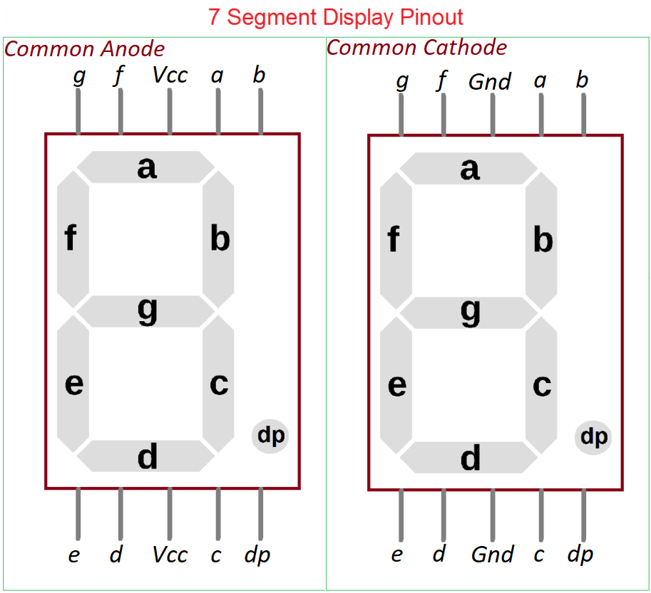
7 Segment Display Pinout
For to pick single digit seven segment display, two options are available one is Common Anode (CA) and another one is Common Cathode (CC). Operation of those two are same, it just make LED glow when it gets bias. Depends on our need and circuit output polarity, we can choose any one.
Due to having 10 or 9 pins, these seven segment displays are using CD4511 (BCD to seven segment display driver IC) and TTL7447 like ICs for converting four digit BCD Inputs to seven segment outputs.
Here we are going to drive a Common Anode 7-Segment display by using ESP32 microcontroller without any driver IC. If you have one, then you can rewrite code to make BCD output through GPIO pins.
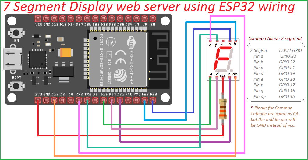
Circuit Diagram
Components Required
- ESP32 Development Board
- Common Anode 7-Segment Display
- Resistor 330 ohms
- Breadboard and Jumper Wires
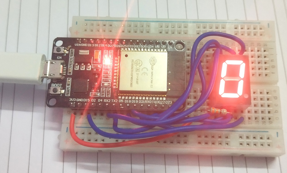
Working Video
Construction & Working
Here we control each segment of the display by connecting it to specific GPIO pins of the ESP32. Through html web page user interface users can select a number to display, which will update in real time on the seven segment display.
ESP32 to 7-Segment Connections:
- Segment ‘a’ -> GPIO 23
- Segment ‘b’ -> GPIO 22
- Segment ‘c’ -> GPIO 21
- Segment ‘d’ -> GPIO 19
- Segment ‘e’ -> GPIO 18
- Segment ‘f’ -> GPIO 17 (TXD 2)
- Segment ‘g’ -> GPIO 16 (RXD 2)
- Decimal Point (DP) -> GPIO 15
So, in the code we are goin to mention the pattern as dp,g,f,e,d,c,b,a each character represents individual segments in display. For example 0b0b11000000 displays 0 (Zero) and 0b11111001 displays 1 (one), that means 0 for ON and 1 for OFF, it is for Common Anode, it will be inverted for Common cathode. Here 0b represents binary in code.
After wiring upload the following code to ESP32 board (Here we used ESP32 DOIT Dev Kit V1) through Arduino IDE. Don’t forget to mention your Wi-Fi Name and Password in code.
7 Segment Display web server using ESP32 Code
#include <WiFi.h>
#include <WebServer.h>
const char* ssid = "Your Wi-Fi SSID";
const char* password = "Your Wi-Fi Password";
const int segmentPins[8] = {23, 22, 21, 19, 18, 17, 16, 15}; // A-G and DP
WebServer server(80);
const byte digitPatterns[10] = {
0b11000000, // 0
0b11111001, // 1
0b10100100, // 2
0b10110000, // 3
0b10011001, // 4
0b10010010, // 5
0b10000010, // 6
0b11111000, // 7
0b10000000, // 8
0b10010000 // 9
};
void displayDigit(int num) {
byte pattern = digitPatterns[num];
for (int i = 0; i < 8; i++) {
digitalWrite(segmentPins[i], (pattern >> i) & 0x01 ? HIGH : LOW);
}
}
String generateHTML() {
String html = "<!DOCTYPE html><html><body>";
html += "<h1>ESP32 7-Segment Display Web Server</h1>";
html += "<h2>theoryCIRCUIT</h2>";
html += "<h3 id='displayText'>Displayed: -</h3>";
html += "<p>Select a number to display:</p>";
for (int i = 0; i < 10; i++) {
html += "<button onclick=\"updateDisplay(" + String(i) + ")\">" + String(i) + "</button> ";
}
html += "<script>";
html += "function updateDisplay(digit) {";
html += " fetch('/display/' + digit).then(response => response.text()).then(text => {";
html += " document.getElementById('displayText').innerText = 'Displayed: ' + digit;";
html += " });";
html += "}";
html += "</script></body></html>";
return html;
}
void handleRoot() {
server.send(200, "text/html", generateHTML());
}
void setup() {
Serial.begin(115200);
delay(1000); // Small delay for Serial Monitor initialization
// Set up the pins for 7-segment display
for (int i = 0; i < 8; i++) {
pinMode(segmentPins[i], OUTPUT);
digitalWrite(segmentPins[i], HIGH); // Initialize all segments to OFF
}
// Connect to Wi-Fi
Serial.println("Connecting to Wi-Fi...");
WiFi.begin(ssid, password);
while (WiFi.status() != WL_CONNECTED) {
delay(500);
Serial.print(".");
}
Serial.println("\nConnected to Wi-Fi!");
Serial.print("ESP32 IP Address: ");
Serial.println(WiFi.localIP());
// Set up the root page
server.on("/", handleRoot);
// Set up routes for each digit (0-9)
for (int i = 0; i < 10; i++) {
server.on("/display/" + String(i), [i]() {
displayDigit(i);
server.send(200, "text/plain", "Displayed: " + String(i));
});
}
// Start the server
server.begin();
}
void loop() {
server.handleClient();
}
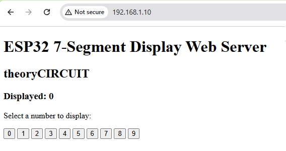
After Uploading, open serial monitor, it may show Wi-Fi status and IP address, if not showing anything then check the baud rate speed and press ‘EN’ button on ESP32 board, Now you will get Wi-Fi status and IP address.
Type the IP address in any browser (That browsing device must be connected to the same Wi-Fi network), you will see the html page and you can now select any number to make display it on seven segment.


