
Last Updated on July 30, 2024
A Development board packed with powerful, easy to use and versatile Microcontroller ESP32 is ESP32 Devkit, It is from Espressif AIoT solution provider. They sell ESP8266 based development board to ESP32-P series boards, that is a board for hobbyist to professionals and Industry. ESP32 chip is based on 32 bit Architecture with dual core processor, Wi-Fi and Bluetooth connectivity, 520KB SRAM, 448KB ROM, External memory Interface support, GPIO Pins, UART, SPI, I2C, Power Management and Security features.
All these features makes ESP32 chip based development board to stand tall from the crowd. A perfect board to start experimenting, Embedded System and Internet of Things (IoT). This board supports Arduino IDE and microPython so it is very easy to code and make it to do something.
If you want to know, how to Interface Arduino IDE with ESP32? or Getting Started to code ESP32 with Arduino IDE! Read here.
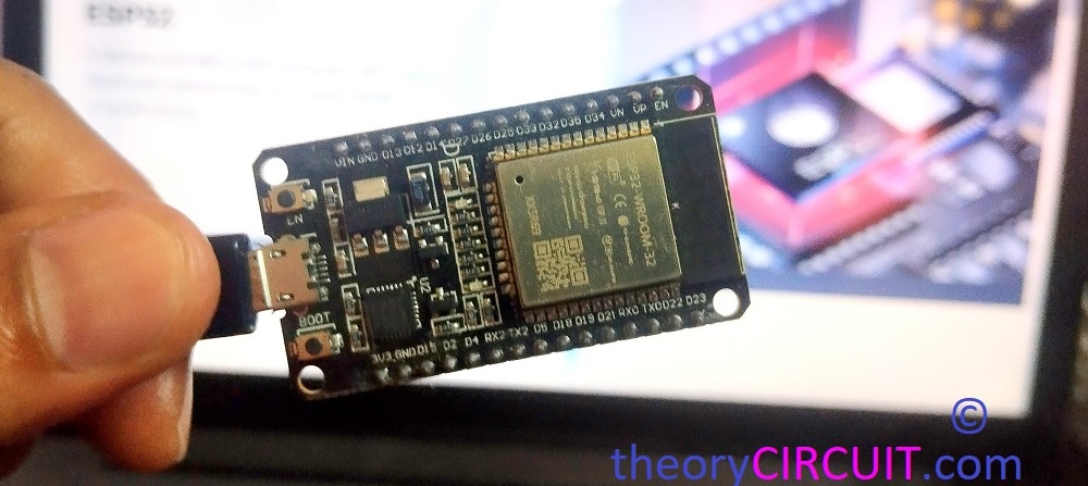
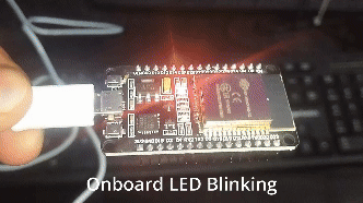
Here we are going to make ESP32 on board LED to blink and fade, this will help you to understand basic GPIO pin function and uploading Arduino sketch to ESP32 dev board. Here we have taken ESP32 Devkit V1 board for this experiment. In this board you will have two LEDs one is for Power supply presence Indication and another one is ON board LED that is connected with GPIO2 Pin. So that we have to mention LED pin as ‘2’ in Arduino code.
Preparation
Hope you have a computer Installed with Arduino IDE and a ESP32 Development board (Devkit V1). First thing you have to Install ESP32 board package in Arduino IDE,
- Open Arduino IDE and Go to File–> Preferences. Then in the “Additional board Manager URLs ” field add the following URL
- https://dl.espressif.com/dl/package_esp32_index.json
- Then click Ok, now go to Tools–> Board–> Boards Manager then search for “ESP32” and then Install the “esp32” by Espressif Systems.
- Connect you ESP32 devkit V1 board to computer (If you already have driver then you will have ‘com’ port number otherwise Install the USB driver if required, depends on your USB bridge Chip in ESP32 dev board.
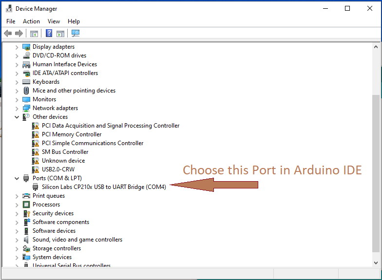
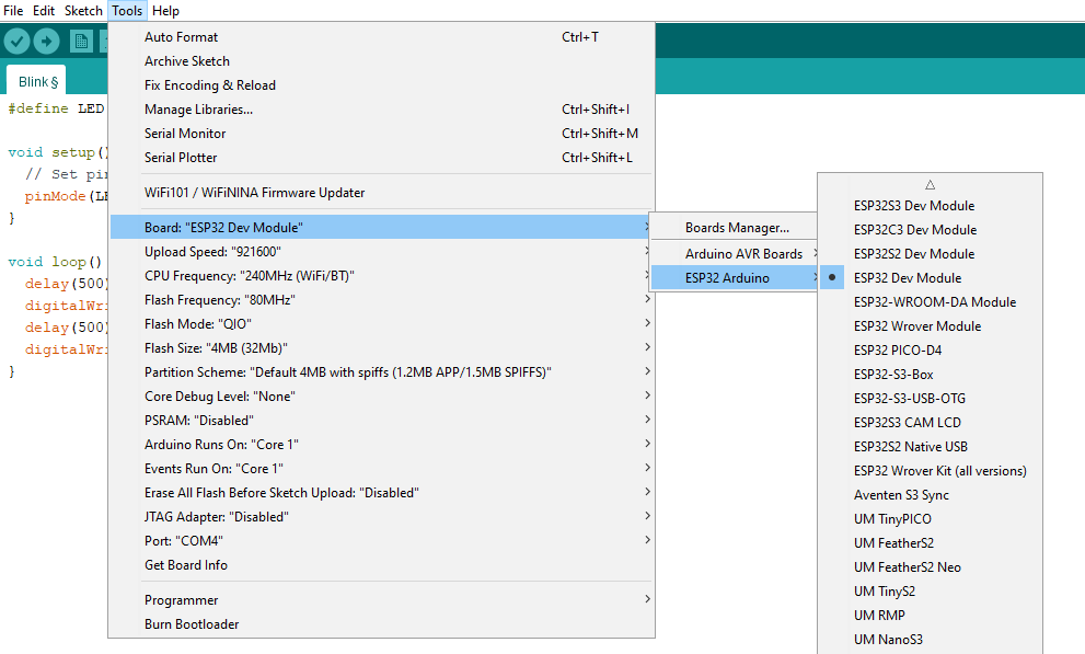
- Then make sure following settings in Arduino IDE.
- Tools–> boards: ESP32 Dev Module
- Upload Speed: 921600, then choose connected port “COM?” ? mark is your pc com port number.
Now its time to upload the Sketch and observe the LED blink.
ESP32 Onboard LED Blink Code
//ESP32 Onboard LED Blink code from www.theorycircuit.com
// Define the LED pin
const int ledPin = 2; // Built-in LED pin on most ESP32 boards

void setup() {
  // Initialize the LED pin as an output
  pinMode(ledPin, OUTPUT);
}

void loop() {
  // Turn the LED on
  digitalWrite(ledPin, HIGH);
  // Wait for a second
  delay(1000);
  // Turn the LED off
  digitalWrite(ledPin, LOW);
  // Wait for a second
  delay(1000);
}
Lets try LED fading effect using PWM. (All the Arduino IDE settings are same for every ESP32 sketch)
ESP32 Onboard LED Fade Code
//ESP32 Onboard LED Blink code from www.theorycircuit.com
// Define the LED pin
const int ledPin = 2; // Built-in LED pin on most ESP32 boards

// Fade parameters
int brightness = 0; // Initial brightness level
int fadeAmount = 5; // Amount to change the brightness level

void setup() {
  // Initialize the LED pin as an output
  pinMode(ledPin, OUTPUT);
}

void loop() {
  // Set the brightness of the LED
  analogWrite(ledPin, brightness);

  // Change the brightness for the next loop iteration
  brightness = brightness + fadeAmount;

  // Reverse the direction of fading if the limits are reached
  if (brightness <= 0 || brightness >= 255) {
    fadeAmount = -fadeAmount;
  }

  // Wait for 30 milliseconds to see the fading effect
  delay(30);
}