
Last Updated on March 16, 2024
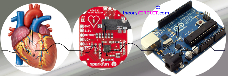
The AD8232 from Analog Devices is a dedicated single lead heart rate monitor front end integrated circuit. The AD8232 is an integrated signal conditioning block for ECG and other biopotential measurement applications. It is designed to extract, amplify, and filter small biopotential signals in the presence of noisy conditions, such as those created by motion or remote electrode placement.
This design allows for an ultralow power analog-to-digital converter (ADC) or an embedded microcontroller to acquire the output signal easily.
Heart
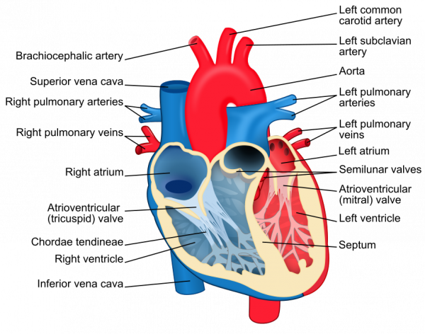
Heart Diagram Credit : Wikipedia.org
Heart Beat with corresponding ECG signal
Heart Beat diagram Credit: Wikipedia.org
What is ECG?
Electrocardiography (ECG or EKG) is the method of recording the electrical activity of heart over a period of time using the electrodes placed on the skin.
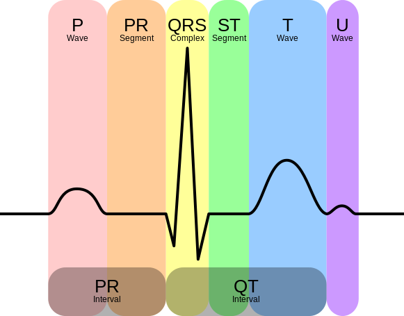
Image Credit: Wikipedia.org
This ECG wave has two sections as PR interval and QT interval, by using the AD8232 IC we can get noise less information.
Heart Monitor AD8232 Board
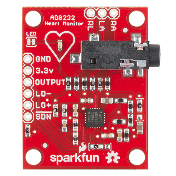
The simple and easy to use breakout board for heart rate monitoring from Sparkfun. This board measures electrical activity of heart through the Electrode pads placed on the skin. By Interfacing this board with Arduino we can get ECG graph through Processing IDE window.
Pin Configuration
| Board Label | Pin Function | Arduino Connection |
| GND | Ground | GND |
| 3.3v | 3.3v Power Supply | 3.3v |
| OUTPUT | Output Signal | A0 |
| LO- | Leads-off Detect – | 11 |
| LO+ | Leads-off Detect + | 10 |
| SDN | Shutdown | Not used |
Electrode Pads
| Cable Color | Signal |
| Black | RA (Right Arm) |
| Blue | LA (Left Arm) |
| Red | RL (Right Leg) |
AD8232 Hookup with Arduino
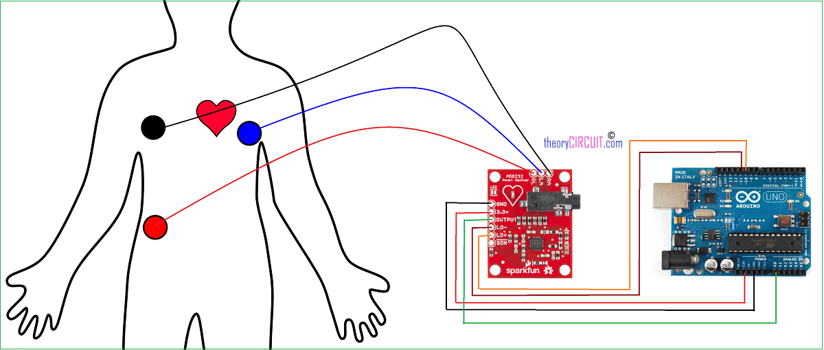
We can use the electrode jack or else pin holes for electrodes. Connect corresponding electrode pads in skin and then provide 3.3V and GND power supply from the Arduino board, the SDN (shutdown) pin is not connected to any part. Output from the breakout board is taken to Arduino’s A0 (Analog input 0) pin. To detect the Leads off situation LO – , LO + are connected to Arduino digital pin D11 and D10 respectively.
Arduino Code
/******************************************************************************
Heart_Rate_Display.inoDemo Program for AD8232 Heart Rate sensor.
Casey Kuhns at SparkFun Electronics 6/27/2014
https://github.com/sparkfun/AD8232_Heart_Rate_Monitor
******************************************************************************/

void setup() {
  // initialize the serial communication:
  Serial.begin(9600);
  pinMode(10, INPUT); // Setup for leads off detection LO +
  pinMode(11, INPUT); // Setup for leads off detection LO -

}

void loop() {

  if((digitalRead(10) == 1)||(digitalRead(11) == 1)){
    Serial.println('!');
  }
  else{
    // send the value of analog input 0:
      Serial.println(analogRead(A0));
  }
  //Wait for a bit to keep serial data from saturating
  delay(1);
}
Processing Code
/******************************************************************************
Heart_Rate_Display.inoDemo Program for AD8232 Heart Rate sensor.
Casey Kuhns at SparkFun Electronics 6/27/2014
https://github.com/sparkfun/AD8232_Heart_Rate_Monitor
******************************************************************************/
import processing.serial.*;

Serial myPort;        // The serial port
int xPos = 1;         // horizontal position of the graph
float height_old = 0;
float height_new = 0;
float inByte = 0;


void setup () {
  // set the window size:
  size(1000, 400);

  // List all the available serial ports
  println(Serial.list());
  // Open whatever port is the one you're using.
  myPort = new Serial(this, Serial.list()[0], 9600);
  // don't generate a serialEvent() unless you get a newline character:
  myPort.bufferUntil('\n');
  // set inital background:
  background(0xff);
}


void draw () {
  // everything happens in the serialEvent()
}


void serialEvent (Serial myPort) {
  // get the ASCII string:
  String inString = myPort.readStringUntil('\n');

  if (inString != null) {
    // trim off any whitespace:
    inString = trim(inString);

    // If leads off detection is true notify with blue line
    if (inString.equals("!")) {
      stroke(0, 0, 0xff); //Set stroke to blue ( R, G, B)
      inByte = 512;  // middle of the ADC range (Flat Line)
    }
    // If the data is good let it through
    else {
      stroke(0xff, 0, 0); //Set stroke to red ( R, G, B)
      inByte = float(inString);
     }

     //Map and draw the line for new data point
     inByte = map(inByte, 0, 1023, 0, height);
     height_new = height - inByte;
     line(xPos - 1, height_old, xPos, height_new);
     height_old = height_new;

      // at the edge of the screen, go back to the beginning:
      if (xPos >= width) {
        xPos = 0;
        background(0xff);
      }
      else {
        // increment the horizontal position:
        xPos++;
      }

  }
}
How to use Processing IDE to Plot Graph?
Please send internal proper circuit diagram of AD8232 for understanding proper functioning of sensor.
Just google it as AD8232, and you can find datasheet further thank you 🙂
myPort = new Serial(this, Serial.list()[2],9600);// Open whatever port is the one you’re using.
In this line, an error is occurring which reads array out of bounds
inByte = map(inByte, 0, 1023, 0, height);
I am facing a problem in this line. On compilation, it showa that NaN cannot render integer value.
please help
Hi Shreyan
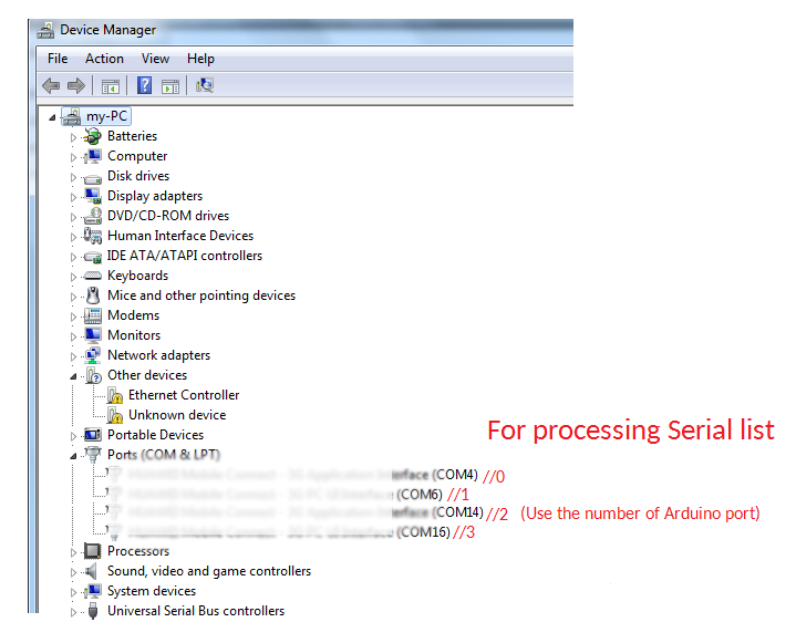
myPort = new Serial(this, Serial.list()[2],9600; the number in red color must be chosen based on the number of ports displayed in you computer.
and you can check out serial plotter with processing here: https://theorycircuit.com/arduino-serial-data-plotter/
hey.
this code doesn’t working..
always show the same error that import name doesn’t exits.what is solution for that??
thank you so much for this code it is very useful.I will do the processing in python and see how it will looks
Hola disculpa la molestia, tengo un problema, me puedes ayudar
Could not parse -1 for –display
COM3 COM4 COM5 COM6 COM7 COM8 COM9 COM10 COM11 COM12 COM13 COM15
mi puerto es el com15
Hello, could you help me please? I run the proyect and only draw lines and shows:
map(NaN, 0, 1023, 0, 400) called, which returns NaN (not a number)
Error, disabling serialEvent() for COM16
null
Thanks
Hello Denisse it’s the same think for me, did you find a solution??
I am facing the same problem.
Where can I find software to view the traces on my computer?
https://processing.org/download/
it’s to dowload the processing programme you need to copy/colle the program and you juste need to press execute, and a window will appear and show this graph
Hello, it’s very helpful thank you so much, i have a question, when i run processing it shows me ” COM4
map(NaN, 0, 1023, 0, 400) called, which returns NaN (not a number) ” in the consol, do you have any idea to how can i make it work???
Hi,
I want to integrate the same ECG sensor with PIC microcontroller, could you please suggest, if I would be able to read the analog signals directly with this sensor or do I need to build an amplifier for reading the analog values from the sensor?
It seems that the error is due to the version 3 of processing. Version 2 should work.
“map(NaN, 0, 1023, 0, 400) called, which returns NaN (not a number) ” in the consol, do you have any idea to how can i make it work???”
hello everyone…
i am getting problem at arduino ide’s serial monitor it’s only showing ! mark after uploading code to arduino…..
is it because minor i have made while connecting arduino and AD8232 ??
if anyone knows how to fix this plz help
Hi, good article. Just one precision, this sensor is not for professional use.
Hello
I cant get any further than the error ;
COM8 map(NaN, 0, 1023, 0, 400) called, which returns NaN (not a number)
Ive only the one COM port, and ive read that the port starts at ‘0’ (zero), so in the line ive added my port,
myPort = new Serial(this, Serial.list()[0], 9600);
but i cant get no further, it seems everyone is having same problem, Can the Admin team shed some light on getting this to work for us please,
Also without the pads connected to body the console show ‘!’, but with pads connected i get numbers ranging 652,0,652,0 and so on…??
Help please !!!!!
Thanks
Hi Rich,
I have the same problem. AD8232 connected to Arduino UNO and this connected to Mac Laptop via USB. The serial data gives numbers ranging 670 to the symbol ! So I see a square wave that is sychronized with my heartbeat but don’t see the normal ECG data.
Did you find a solution?
Thank you,
Ignacio
Sorry to add another post, I forgot to ask something else.
I see that the initial code is uploaded to the Arduino, but why, what purpose is the use of
the Processing application. Why cannot the whole code be processed by just uploading the sketch to the Arduino.? I’m new to the Processing application, and at present learning about it. Going back to my last post, could the error(s) be anything to do with PC’s running Windows 10?, as all or most systems now run the OS. I may be barking up the wrong tree, but will try out on a system I have here on Win 7. Also I did get just before the error occurred,
vertical lines rather than horizontal, there was a long, then a line half that, then a small line.
Thanks for your time, hope you can return some help in order for us to have this project
Working.
Rich
Where should I buy the cable with the three sensors?
Regards,
Franz
Hi Franz
If your querie is the pads and cable, I bought my AD8232 module and it came with the lead and 3 pads, from EBay, user Cayin35. As these were one time use I also purchased
11 re-useable pads again EBay for 99 pence, and agcain, for 10 snap on type for £3.35
As a side note, in the beginning I was going to make the cable myself, stereo 3.5 plug with screened cable, and use crocodile clips instead, but for the prices above it wasn’t worth it.
I hope I’ve helped in some way for you.
Rich
Hello.
I’m having trouble with this , the sensor reads values but it goes from 0 to 650 (+/- 50), and the signal is a square wave. it seams that it can detect a pulse but in digital instead of analog. Any one can help?
thanks in advance.
Hi, someone find a solution to problem of “square wave” (0/650) in 3.3v??
Hello Ignacio Serrano
Ive just only got back to playing with this project, as i was away and also was waiting for extra ECG pads.
Ive nothing to add for you, but I hate being beaten by projects, so I hope with some other members on here we can sort this problem out. I am a bit confused why Admin has not come back to help us in some way.
However, if i do get something of interest for you, i will pass it on.
Thanks
Rich
Hello
After I sent my last post, i had a thought regarding the version of Processing. I was using up to now 3.3.7. So with a little Googling , i found what i suspected. The code version looks as if it needs version 2.2.1 of Processing. Reading its seems it wont run on version 3.0.2 and thereafter..
Its now working, not brilliant,, the graphics are not solid. but I am happy its working.
Go here for a read – https://learn.sparkfun.com/tutorials/ad8232-heart-rate-monitor-hookup-guide/discuss
So, finally got it to work, but surely this cant be the only way to use the AD8232 with this small piece of code, even though it is good.
Have fun
Rich
Hello
Am also working on the same project and came across similar challenge and now I have tried to downlaod version 2.2.1 of processing but I am not winning.
What is the statement “exit status 1
Variable or field ‘seriaEvent’ declared void” means ?
How to fix it?
How to process the signal using LabVIEW? Could you please help us with the LabVIEW block diagram.
Awaiting your reply.
I would like to send the electrocardiogram with a bluetooth module hc 05 to another how could I solve the problem?
I am getting the following output when using a delay of 1000
https://drive.google.com/file/d/1cnLqDhcAouCkwtG5XxYNm9Ohjl6B_eYz/view?usp=sharing
when using no delay I am getting the following output
https://drive.google.com/file/d/1b1cKkYbTDJWm87cgVC_-ADvXxo4mr1l-/view?usp=sharing
Can anyone advise me suggestion?
thanks in advance
Why we basically use 3 lead in AD8232 ?Why not 12 lead ?
I want to interface the heart rate ecg module to Arduino nano I tried to interface the connection but the plot in serial monitoring was displays only one minute otherwise it was not working , please give solution to draw the plot in continuous plotting for ecg module thank you.
I want to interface the heart rate ecg module to Arduino nano I tried to interface the connection but the plot in serial monitoring was displays only one minute otherwise it was not working