
Last Updated on March 24, 2024
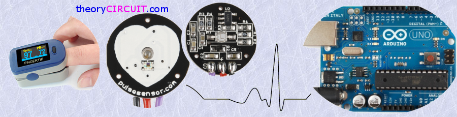
Heart Rate data can be used in many Electronic design and microcontroller projects. But the heart rate data is difficult to read, however the Pulse Sensor Amped help us to read heart rate. The Pulse Sensor Amped is a plug-and-play heart-rate sensor for Arduino. Pulse sensor Arduino project is easy to construct and It can be used by students, artists, athletes, makers, and game & mobile developers who want to easily incorporate live heart-rate data into their projects.
It essentially combines a simple optical heart rate sensor with amplification and noise cancellation circuitry making it fast and easy to get reliable pulse readings.
Pulse Sensor Schematic
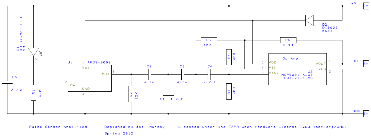
Here the APDS-9008 Miniature surface Mount Ambient light photo sensor from Avago technologies plays an important role and it is responsible to detect concentration of Light bounces back through fingertip or earlobe. D1 LED gives light source for this operation. Signal from the ambient light sensor amplified through op Amp and the signal is ready to read by the microcontroller.
The pulse Sensor Kit
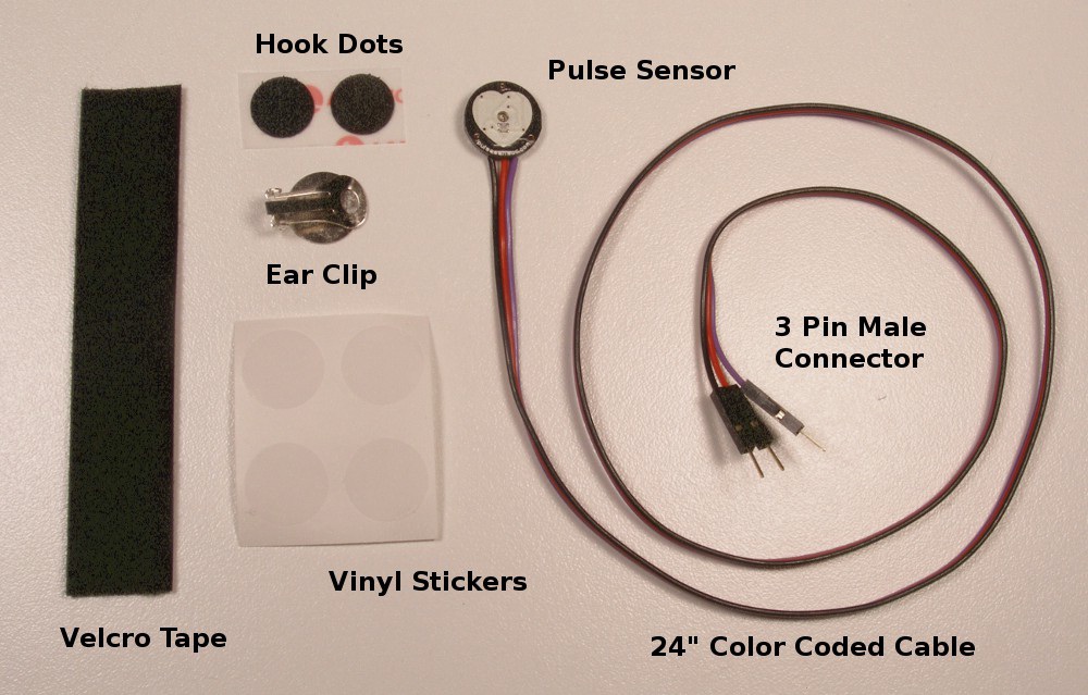
The pulse sensor amped kit Available in
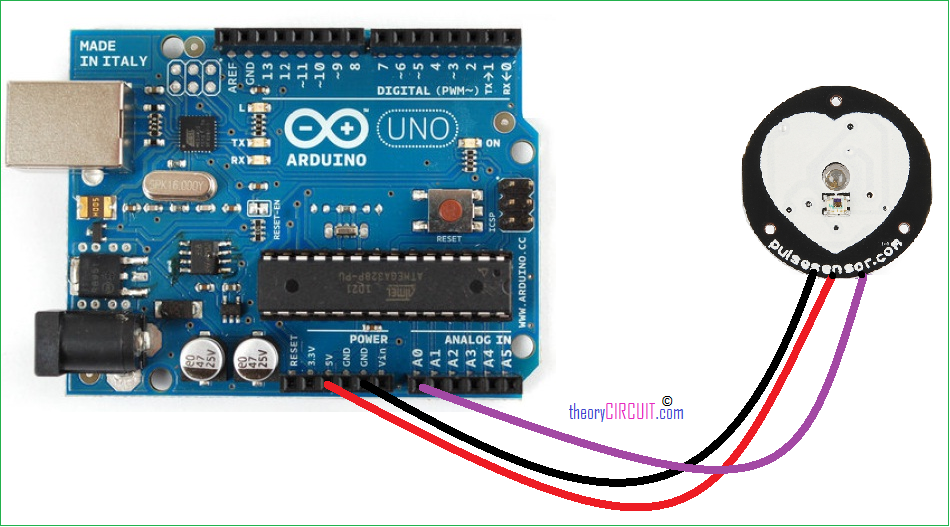
Pulse Sensor Arduino Hookup
Pulse Sensor Arduino Components
- Arduino Board (here Arduino uno)
- Pulse Sensor Arduino kit
- Connecting Wires
- USB cable
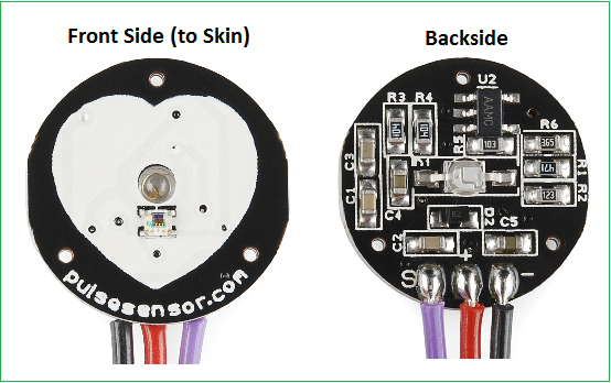
Connect the sensor’s power supply pins to the arduino board supply pin as Red – 5V, Black – GND and Purple – A0 (analog input 0) its over. This Analog input reading can be displayed in serial terminal of Arduino IDE or it can be drawn as pulse by using Processing IDE.
Pulse Sensor Arduino Code
/*>> Pulse Sensor Amped 1.2
<<This code is for Pulse Sensor Amped by Joel Murphy and Yury Gitman www.pulsesensor.com
Check here for detailed code walkthrough:
http://pulsesensor.myshopify.com/pages/pulse-sensor-amped-arduino-v1dot1
Code Version 1.2 by Joel Murphy & Yury Gitman  Spring 2013
This update fixes the firstBeat and secondBeat flag usage so that realistic BPM is reported. theoryCIRCUIT.com */


//  VARIABLES
int pulsePin = 0;                 // Pulse Sensor purple wire connected to analog pin 0
int blinkPin = 13;                // pin to blink led at each beat
int fadePin = 5;                  // pin to do fancy classy fading blink at each beat
int fadeRate = 0;                 // used to fade LED on with PWM on fadePin


// these variables are volatile because they are used during the interrupt service routine!
volatile int BPM;                   // used to hold the pulse rate
volatile int Signal;                // holds the incoming raw data
volatile int IBI = 600;             // holds the time between beats, must be seeded!
volatile boolean Pulse = false;     // true when pulse wave is high, false when it's low
volatile boolean QS = false;        // becomes true when Arduoino finds a beat.


void setup(){
  pinMode(blinkPin,OUTPUT);         // pin that will blink to your heartbeat!
  pinMode(fadePin,OUTPUT);          // pin that will fade to your heartbeat!
  Serial.begin(115200);             // we agree to talk fast!
  interruptSetup();                 // sets up to read Pulse Sensor signal every 2mS
   // UN-COMMENT THE NEXT LINE IF YOU ARE POWERING The Pulse Sensor AT LOW VOLTAGE,
   // AND APPLY THAT VOLTAGE TO THE A-REF PIN
   //analogReference(EXTERNAL);
}


void loop(){
  sendDataToProcessing('S', Signal);     // send Processing the raw Pulse Sensor data
  if (QS == true){                       // Quantified Self flag is true when arduino finds a heartbeat
        fadeRate = 255;                  // Set 'fadeRate' Variable to 255 to fade LED with pulse
        sendDataToProcessing('B',BPM);   // send heart rate with a 'B' prefix
        sendDataToProcessing('Q',IBI);   // send time between beats with a 'Q' prefix
        QS = false;                      // reset the Quantified Self flag for next time
     }

  ledFadeToBeat();

  delay(20);                             //  take a break
}


void ledFadeToBeat(){
    fadeRate -= 15;                         //  set LED fade value
    fadeRate = constrain(fadeRate,0,255);   //  keep LED fade value from going into negative numbers!
    analogWrite(fadePin,fadeRate);          //  fade LED
  }


void sendDataToProcessing(char symbol, int data ){
    Serial.print(symbol);                // symbol prefix tells Processing what type of data is coming
    Serial.println(data);                // the data to send culminating in a carriage return
  }
Pulse Sensor Processing Code
/*
THIS PROGRAM WORKS WITH PulseSensorAmped_Arduino-xx ARDUINO CODE
THE PULSE DATA WINDOW IS SCALEABLE WITH SCROLLBAR AT BOTTOM OF SCREEN
PRESS 'S' OR 's' KEY TO SAVE A PICTURE OF THE SCREEN IN SKETCH FOLDER (.jpg)
MADE BY JOEL MURPHY AUGUST, 2012
*/


import processing.serial.*;
PFont font;
Scrollbar scaleBar;

Serial port;

int Sensor;      // HOLDS PULSE SENSOR DATA FROM ARDUINO
int IBI;         // HOLDS TIME BETWEN HEARTBEATS FROM ARDUINO
int BPM;         // HOLDS HEART RATE VALUE FROM ARDUINO
int[] RawY;      // HOLDS HEARTBEAT WAVEFORM DATA BEFORE SCALING
int[] ScaledY;   // USED TO POSITION SCALED HEARTBEAT WAVEFORM
int[] rate;      // USED TO POSITION BPM DATA WAVEFORM
float zoom;      // USED WHEN SCALING PULSE WAVEFORM TO PULSE WINDOW
float offset;    // USED WHEN SCALING PULSE WAVEFORM TO PULSE WINDOW
color eggshell = color(255, 253, 248);
int heart = 0;   // This variable times the heart image 'pulse' on screen
//  THESE VARIABLES DETERMINE THE SIZE OF THE DATA WINDOWS
int PulseWindowWidth = 490;
int PulseWindowHeight = 512;
int BPMWindowWidth = 180;
int BPMWindowHeight = 340;
boolean beat = false;    // set when a heart beat is detected, then cleared when the BPM graph is advanced


void setup() {
  size(700, 600);  // Stage size
  frameRate(100);
  font = loadFont("Arial-BoldMT-24.vlw");
  textFont(font);
  textAlign(CENTER);
  rectMode(CENTER);
  ellipseMode(CENTER);
// Scrollbar constructor inputs: x,y,width,height,minVal,maxVal
  scaleBar = new Scrollbar (400, 575, 180, 12, 0.5, 1.0);  // set parameters for the scale bar
  RawY = new int[PulseWindowWidth];          // initialize raw pulse waveform array
  ScaledY = new int[PulseWindowWidth];       // initialize scaled pulse waveform array
  rate = new int [BPMWindowWidth];           // initialize BPM waveform array
  zoom = 0.75;                               // initialize scale of heartbeat window

// set the visualizer lines to 0
 for (int i=0; i<rate.length; i++){
    rate[i] = 555;      // Place BPM graph line at bottom of BPM Window
   }
 for (int i=0; i<RawY.length; i++){
    RawY[i] = height/2; // initialize the pulse window data line to V/2
 }

// GO FIND THE ARDUINO
  println(Serial.list());    // print a list of available serial ports
  // choose the number between the [] that is connected to the Arduino
  port = new Serial(this, Serial.list()[0], 115200);  // make sure Arduino is talking serial at this baud rate
  port.clear();            // flush buffer
  port.bufferUntil('\n');  // set buffer full flag on receipt of carriage return
}

void draw() {
  background(0);
  noStroke();
// DRAW OUT THE PULSE WINDOW AND BPM WINDOW RECTANGLES
  fill(eggshell);  // color for the window background
  rect(255,height/2,PulseWindowWidth,PulseWindowHeight);
  rect(600,385,BPMWindowWidth,BPMWindowHeight);

// DRAW THE PULSE WAVEFORM
  // prepare pulse data points
  RawY[RawY.length-1] = (1023 - Sensor) - 212;   // place the new raw datapoint at the end of the array
  zoom = scaleBar.getPos();                      // get current waveform scale value
  offset = map(zoom,0.5,1,150,0);                // calculate the offset needed at this scale
  for (int i = 0; i < RawY.length-1; i++) {      // move the pulse waveform by
    RawY[i] = RawY[i+1];                         // shifting all raw datapoints one pixel left
    float dummy = RawY[i] * zoom + offset;       // adjust the raw data to the selected scale
    ScaledY[i] = constrain(int(dummy),44,556);   // transfer the raw data array to the scaled array
  }
  stroke(250,0,0);                               // red is a good color for the pulse waveform
  noFill();
  beginShape();                                  // using beginShape() renders fast
  for (int x = 1; x < ScaledY.length-1; x++) {
    vertex(x+10, ScaledY[x]);                    //draw a line connecting the data points
  }
  endShape();

// DRAW THE BPM WAVE FORM
// first, shift the BPM waveform over to fit then next data point only when a beat is found
 if (beat == true){   // move the heart rate line over one pixel every time the heart beats
   beat = false;      // clear beat flag (beat flag waset in serialEvent tab)
   for (int i=0; i<rate.length-1; i++){
     rate[i] = rate[i+1];                  // shift the bpm Y coordinates over one pixel to the left
   }
// then limit and scale the BPM value
   BPM = min(BPM,200);                     // limit the highest BPM value to 200
   float dummy = map(BPM,0,200,555,215);   // map it to the heart rate window Y
   rate[rate.length-1] = int(dummy);       // set the rightmost pixel to the new data point value
 }
 // GRAPH THE HEART RATE WAVEFORM
 stroke(250,0,0);                          // color of heart rate graph
 strokeWeight(2);                          // thicker line is easier to read
 noFill();
 beginShape();
 for (int i=0; i < rate.length-1; i++){    // variable 'i' will take the place of pixel x position
   vertex(i+510, rate[i]);                 // display history of heart rate datapoints
 }
 endShape();

// DRAW THE HEART AND MAYBE MAKE IT BEAT
  fill(250,0,0);
  stroke(250,0,0);
  // the 'heart' variable is set in serialEvent when arduino sees a beat happen
  heart--;                    // heart is used to time how long the heart graphic swells when your heart beats
  heart = max(heart,0);       // don't let the heart variable go into negative numbers
  if (heart > 0){             // if a beat happened recently,
    strokeWeight(8);          // make the heart big
  }
  smooth();   // draw the heart with two bezier curves
  bezier(width-100,50, width-20,-20, width,140, width-100,150);
  bezier(width-100,50, width-190,-20, width-200,140, width-100,150);
  strokeWeight(1);          // reset the strokeWeight for next time


// PRINT THE DATA AND VARIABLE VALUES
  fill(eggshell);                                       // get ready to print text
  text("Pulse Sensor Amped Visualizer 1.1",245,30);     // tell them what you are
  text("IBI " + IBI + "mS",600,585);                    // print the time between heartbeats in mS
  text(BPM + " BPM",600,200);                           // print the Beats Per Minute
  text("Pulse Window Scale " + nf(zoom,1,2), 150, 585); // show the current scale of Pulse Window

//  DO THE SCROLLBAR THINGS
  scaleBar.update (mouseX, mouseY);
  scaleBar.display();

//
}  //end of draw loop
Check here to know how to use Processing IDE
Get Code: PulseSensorAmpd_Processing_1dot1_2
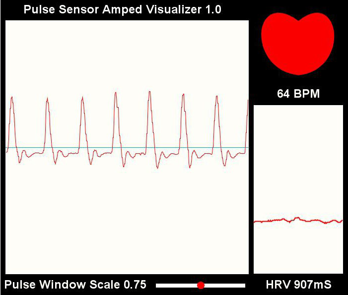
Screenshot
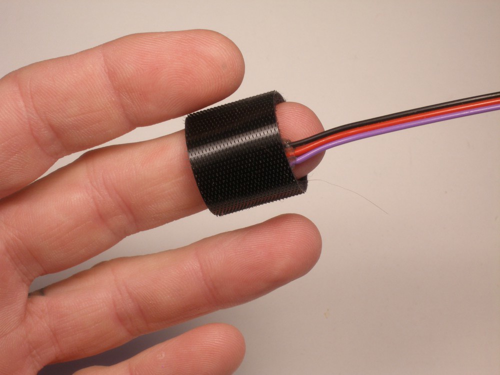
Image Credit: pulsesensor.com
Scrollbar scaleBar;
this class is not present.
it is saying doesnt exist please help.
hey give me ans of that
Download the code from the get code link before the screenshot
give me ans if u got.
Where is the interruptSetup() function?
Iam tried to calculate the bpm using Heart-rate sensor values the output was occured in serial monitoring and graphical output also occured I tried to convert the bpm values stored in array bpm samples but I don’t know how to take average bpm value if anybody know right solution ???