Last Updated on March 25, 2024
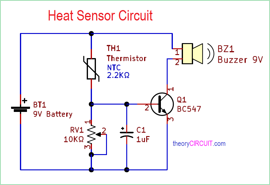
Simple heat sensor circuit designed to give alert sound when the temperature reaches the desired threshold, here we can adjust the temperature threshold level using Variable resistor RV1. This simple circuit is easy to construct and test.
This circuit utilize NTC (Negative Temperature Coefficient) thermistor hence the Resistance value of this device decrease when the temperature rises.
Circuit Diagram
Components Required
- NTC thermistor 2.2KΩ
- Variable Resistor 10KΩ
- Transistor BC547 (NPN)
- Buzzer 9V
- Capacitor 1uF/16V
- Battery 9V
Construction & Working
In this circuit NPN transistor BC547 acts as a switch and it turn ON buzzer when the temperature rises over the threshold and turn OFF buzzer when the temperature below the threshold. The NTC themistor 2.2K is connected with the Variable resistor and Base terminal of Transistor Q1. Hence the base of Q1 gets bias through thermistor and variable resistor. Here RV1 resistance value decides the temperature threshold. Buzzer element is connected with battery and transistor collector terminal.
If there is no temperature source are rise of temperature then the TH1 thermistor gives full resistance the bias from battery to base terminal of transistor, when the temperature gets rise then Resistance value of TH1 gets decrease and allows bias from battery to base terminal of transistor, then transistor gets turn ON and makes the buzzer sound.
Thermistor – BC547 pindetails

Thermistor are available in two categories like 1. PTC and 2. NTC, Thermistors will have only two terminals and has no polarity.
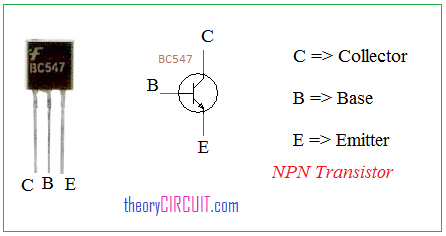
BC547 is a NPN transistor with three terminals and useful for low power switching and amplification circuits.
Hi guys, thanks for the bright information but l would like to know how to make a buzzer produce sound at a fixed temperature of 70°C around thermistor
This heat sensor circuit designed to give alert sound when the temperature reaches the desired threshold, here you can adjust the temperature threshold level using Variable resistor RV1. You have to measure using external thermometer to set 70°C and this circuit gives approximate output. If you want exact sensing then try using microcontroller and LM 35 sensor. https://theorycircuit.com/temperatur-sensor-lm35-with-arduino/