
Last Updated on March 16, 2024
Darkness detector circuit can be used as a alarm circuit or as a watchdog circuit and it can be used in so many ways. We can employ this circuit where we need to know the change in light intensity or darkness.
This circuit is constructed with LDR (Light Dependent Resistor) and timer IC 555, It will produce buzzer beep sound when the shadow or darkness occurs on the LDR.
Here this circuit uses 555 as a Astable multivibrator and then the output square pulses are converted into alert sound by piezo buzzer.
LDR
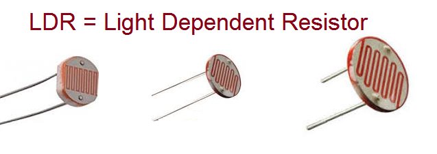
The LDR or Light Dependent Resistor is also called as photo Resistor. It comes in different size from 5mm to 20mm depends on the LDR size sensitivity may change slightly. The LDR changes its Resistance value depends on light intensity if there is no light then it becomes MΩ Resistor, if light falls on it then it may become few Ω Resistor, using this character following circuit is designed to detect darkness.
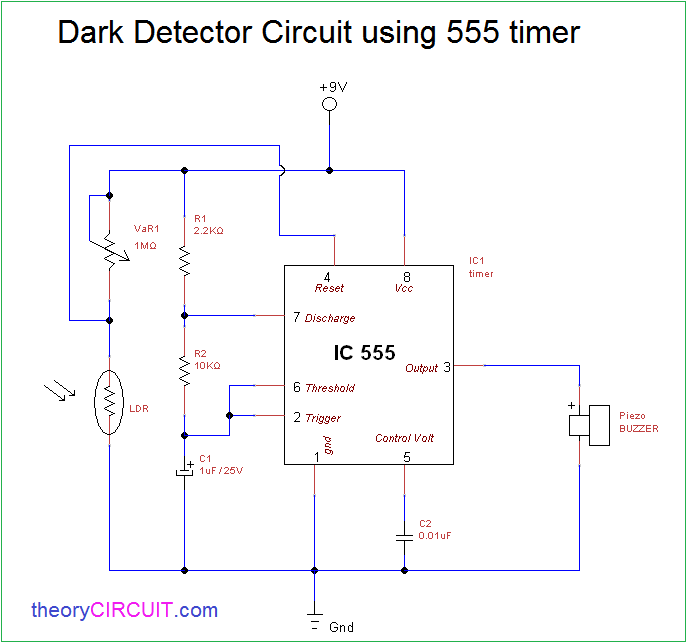
Dark detector Circuit Diagram
Components Required
- IC 555
- LDR (Any size)
- piezo buzzer
- variable Resistor 1MΩ
- Resistor 2.2KΩ, 10KΩ each one
- Capacitor 1uF/25V, 0.01uF each one
- 9V battery
- Connecting wires
Construction & Working
The timer IC 555 connected with components as a Astable multivibrator except reset pin, so the timing Resistors R1, R2 and timing capacitor C1 are connected between Vcc and Gnd then discharge pin is connected between R1 & R2 then threshold, trigger pins are commonly connected between R2 and C1.
The LDR is connected with variable Resistor VaR1 and Reset pin is connected between VaR1 and LDR. Power supply is applied to the LDR through VaR1 and hence we can change the sensitivity level of LDR through variable resistor VaR1. When the LDR detects the darkness then timer IC 555 gets Reset signal and starts to produce square pulse at output pin, this may drive buzzer and produce beep sound.
Note:-
- You need to calibrate the circuit to detect exact darkness.
- It produce buzzer sound for few seconds, you can change output time by changing C1 Value.