Last Updated on December 6, 2024
Red Blue LED Police Flasher Circuit can be easily constructed by using Two Timer 555 ICs and two NPN Transistors. To bring the pattern of Police Lights, we need to make Red LEDs flasing minimum Three times and Blue LEDs three time and then repeating it continuously. So that we need to have two Astable Multivibrators to produce long pulse (3 seconds) and short pulse (1 Second). LEDs will produce light and intensity depends on the supply and current level. Output voltage and current from the Timer IC 555 is not enough to drive more that two LEDs efficiently. So here we introduced Transistor Switch to draw voltage and current from power supply rail depends on the base input from Timer IC 555.
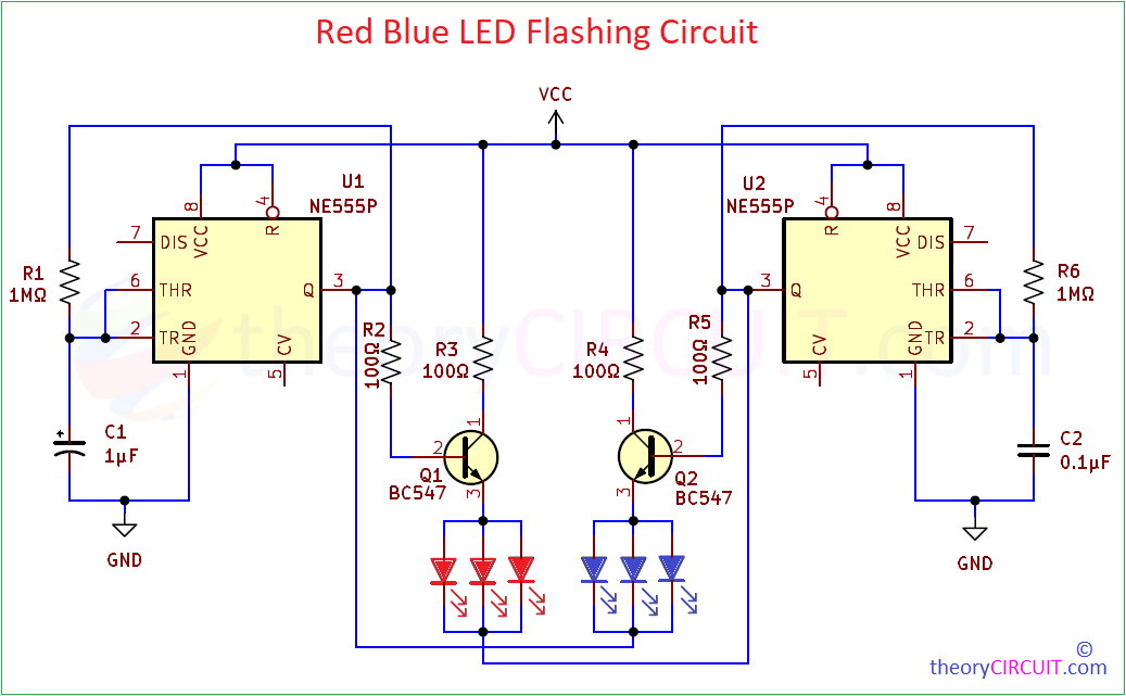
Two BC547 NPN Transistors Collector terminals are connected to the Positive supply (VCC) and Q1 base is connected with output pin of U1 555, Q2 Transistor base is connected with U2 555 output pin. Here we have used Three Red and Three blue LEDs, you can connect more depends on the voltage and current of power supply and also consider the maximum current capability of switching transistors.
Circuit Diagram
Components Required for Flashing Police Light Circuit
- Timer IC NE555P = 2
- BC547 NPN Transistor = 2
- Red LEDs = 3
- Blue LEDs = 3
- Resistors 1MΩ = 2, 100Ω = 4
- Capacitors 1µF = 1, 0.1µF = 1
- Power Supply VCC = 5V to 9V
Working!
Construction & Working
As previously said, to create Police Strobe Lights effect we need to make Red and Blue LEDs blink alternatively. For to achieve this we used two different Astable multivibrators made with Timer IC 555. Here the First Timer IC U1 uses 1MΩ Resistor and 1μF Capacitor as timing element to produce approximately 3 Seconds timing pulse and Timer IC U2 uses 1MΩ Resistor and 0.1μF Capacitor as timing element to produce approximately 1 Second timing pulse. Each 555 timing elements have feedback from output.
To make bright light from LEDs we used Transistors and Anode terminals of three Red and Blue LEDs connected with Q1 and Q2 emitter and the Cathode terminals are connected to opposite timer IC output pin. Here Red LEDs turn ON and blink during Positive Cycle from U1 timer IC and Negative Cycle from U2 Timer IC. During this time Blue LEDs stays in OFF condition.
Blue LEDs turn ON and blink during Negative Cycle from U1 timer IC and Positive Cycle from U2 Timer IC. During this time Red LEDs stays in OFF condition.
Square Pulse Output from Timer IC
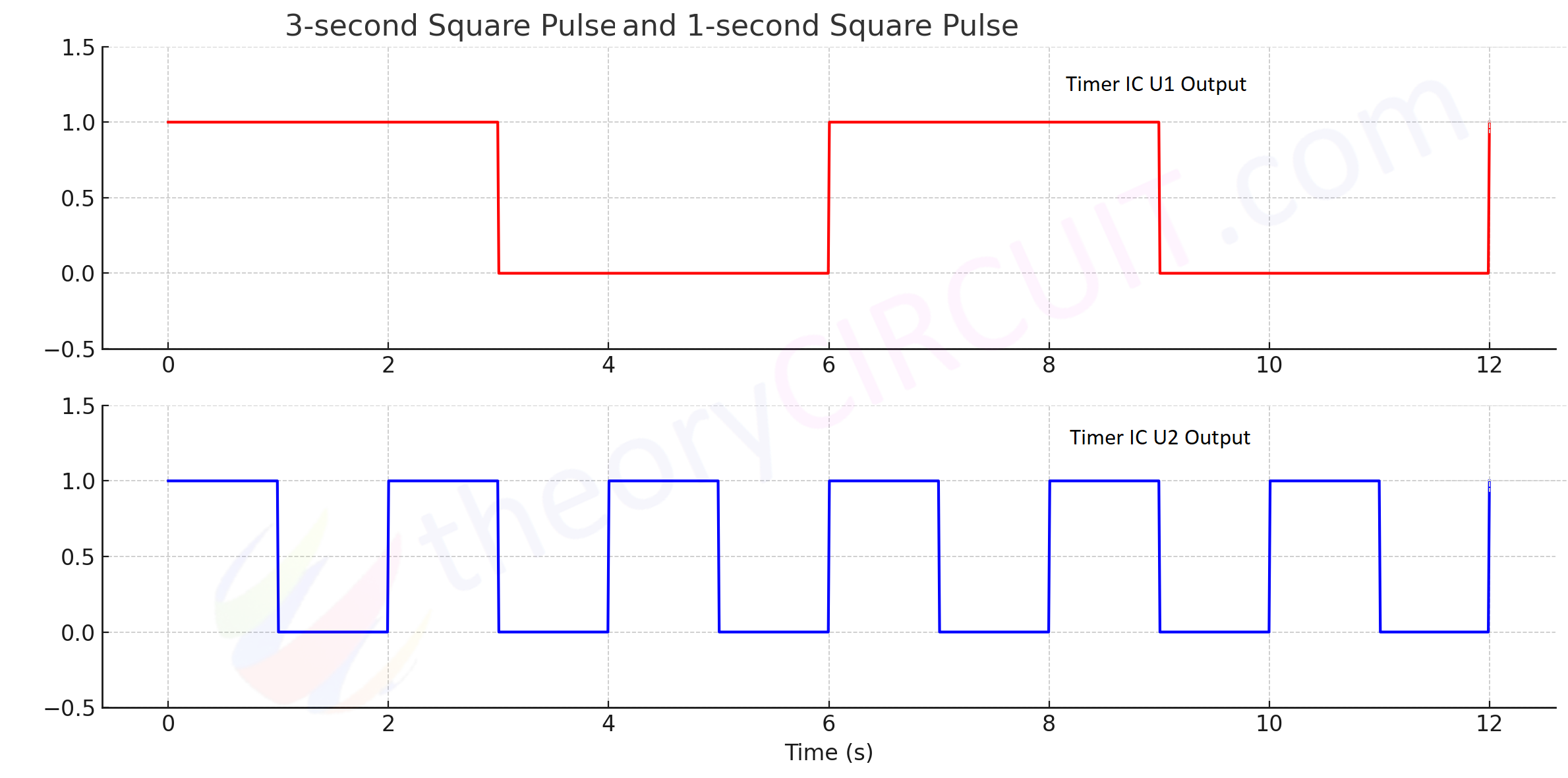
Here both U1 and U2 timer ICs are configured in Astable Multivibrator mode so this blinking operation continuously occurs.
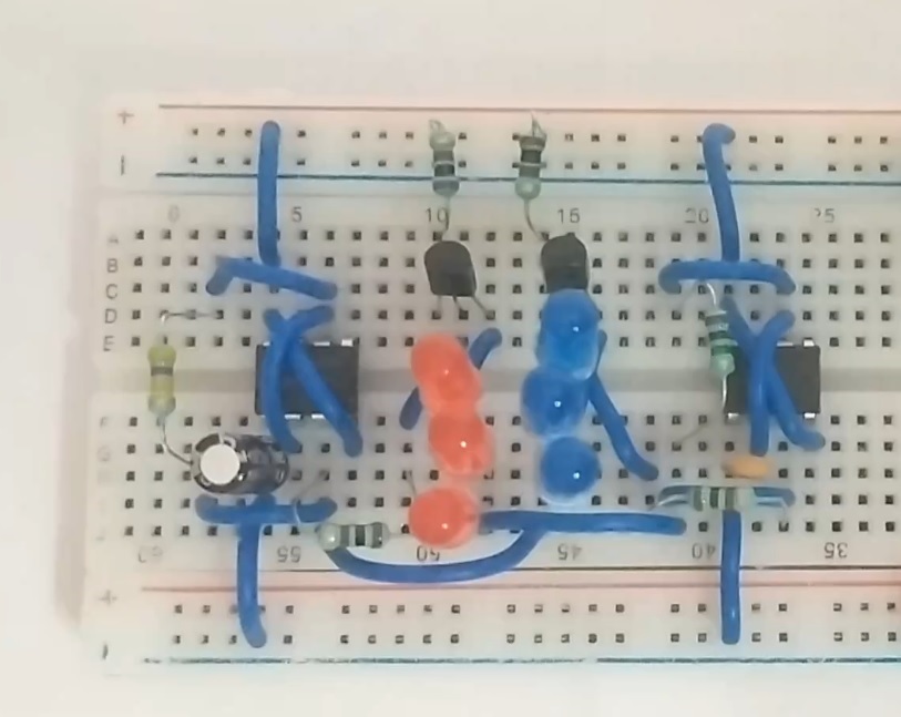
Breadboard Prototype