
Last Updated on March 29, 2024
Timer IC 555 can be configured in different types of modes and can be used in many applications, for electronics learners and experienced persons Timer IC 555 might be the most favourite component. With this single IC we can create tons of useful applications and circuits (IC 555 Circuits). As we know Timer IC 555 can be operated in basic three modes they are, 1. Astable, 2. Monostable and 3. Bistable. Here stable represents the output signal condition, either it frequently change or being stable upto trigger occurs. In the following circuit IC 555 configured in bistable mode and trying to control single LED.
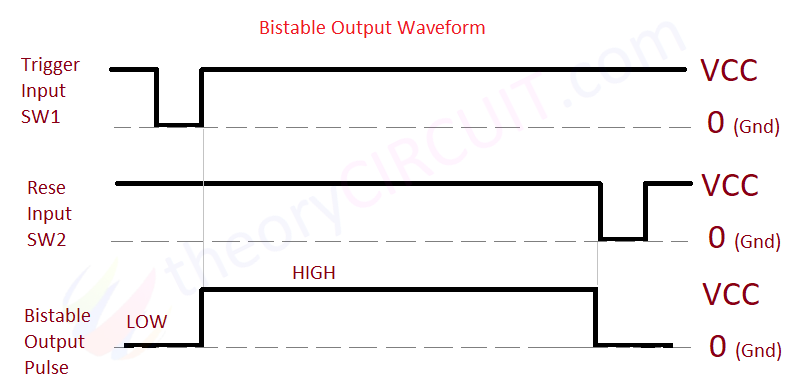
Let us understand Bistable Multivibrators before jump into 555 Timer Bistable Multivibrator Circuit, These are circuits capable of maintaining one of two stable states indefinitely either HIGH or LOW. With the help of Trigger and Reset inputs, these circuit changes its present state to another state. Looks similar to flip-flops, yes it is kind of that.
IC 555
In its basic blocks 555 timer consists of two voltage comparators called upper and lower, then SR flip-flop, a discharge transistor, and a resistor divider network with the value of 5K 5K 5K (may be this is the reason behind its name).
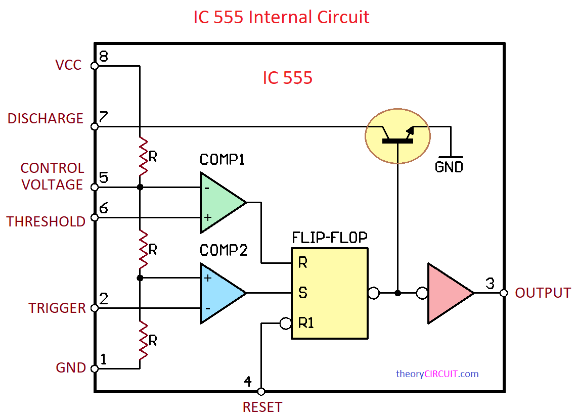
Most common package of IC 555 is DIP 8 (Dual Inline Package), and the pin functions of Timer IC,
| Pin Number | Pin Name | Pin Function |
| 1 | GND | Ground Supply Pin (DC Supply – Ve pin) |
| 2 | Trigger | Trigger pin, When the voltage at this pin drops below 1/3 of Vcc, it triggers the internal flip-flop. |
| 3 | Output | Main Output Pin |
| 4 | Reset | The Reset pin is used to reset the internal flip-flop, Active LOW, Forces output to go LOW. |
| 5 | Control Voltage | Control Voltage pin to control the timing characteristics like duty cycle of pulse. |
| 6 | Threshold | Threshold pin, When the voltage at this pin rises above 2/3 of Vcc, then it resets the internal flip-flop. |
| 7 | Discharge | Discharge pin, used to discharge the external Timing capacitor. |
| 8 | VCC | VCC Pin, Positive supply pin of 555, It takes 4.5V to 15V as bias. |
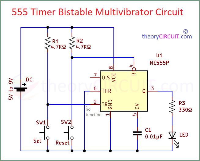
SET and RESET Switch Bistable Circuit
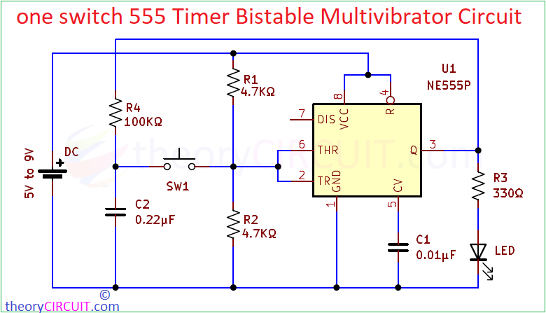
One Switch Bistable Circuit
Components Required
- Timer IC 555
- LED
- Resistor 4.7KΩ = 2, 330Ω =1, 100KΩ = 1
- Tactile Push Button Switch = 2
- Capacitor 0.01μF (103) and 0.22μF (224)
- DC supply
- breadboard
- Connecting wires
Working!
Construction & Working
This Bistable mode of operation requires minimum component to setup, Here we used LED to indicate the stable output (Glow = HIGH and OFF = LOW), you can use any output actuator or relay to control applications. Trigger pin and Reset pins are connected with Switch throug R1 and R2 Resistors, SW1 and SW2 are Tactile Push Button Switch, that means it makes connection when pushed and opens when leave. When the power supply given, this circuit stays in LOW output state and so LED will be OFF.
When you press Set switch then supply to the Trigger pin through R1 Resistor falls to Ground below 1/3 of VCC and it makes the internal flip to Set and output goes to HIGH state. This HIGH state remains until Reset input occurs. Because we already Grounded (GND) the threshold pin. So the upper comparator won’t reset internal flip flop.
When you press Reset pin, Ground (GND) supply reaches Active low Reset pin of internal flip flop and makes Reset, Output goes to LOW. This LOW output state remains until trigger input occurs.
One Switch Bistable Circuit, uses only one switch to make Bistable output, it uses feedback from output and uses Trigger pin (Set) and Threshold pin (Reset) at same time. When the output is low, trigger pin makes internal flip flop to set when we press Switch, during High time Capacitor C2 gets charged through R4 Resistor. If we press the same switch now the charge in C2 will be above 2/3 of Vcc and makes the threshold pin to Reset the internal flip-flop.