Last Updated on March 16, 2024
Most circuits are designed with transistors and different parameter transistors are being used in many circuits and prototypes. If you debugging a circuit to find fault in most case you have to check the transistor condition, by the same way it is better practice to test and implement the transistor in circuits.
Here simple transistor tester circuit using 555 timer designed to test all kind of transistors, this schematic has one indicator LED and it will blink if the transistor works good, and stays in off condition if the transistor open or not working.
Circuit Diagram
Prototype Video
Components Required
- IC 555
- LED
- Resistors 1KΩ = 2, 100Ω, 2KΩ
- Variable Resistor 10KΩ
- Capacitor 100μF, 0.01μF
- Battery 9V
- Test transistor either NPN or PNP
Construction & Working
Here the transistor tester circuit using 555 timer works as a Astable Multivibrator circuit and produce square pulse output depends on the timing Resistor and timing Capacitor value. Output of this circuit is connected with the T2 test point, Positive supply is connected to the T1 test point through R4 Resistor and LED, Negative supply is connected to the T3 test point.
We know every transistor acts as a switch and here the NPN or PNP transistors placed in the test point then output pulse from astable multivibrator drives the base of test transistor and makes the test transistor ON and OFF repeatedly hence the LED starts blink if so, then it can be considered as a working transistor. If the test transistor opened or not working then LED stays in OFF condition.
NOTE:- Test the circuit with Known good transistor (NPN and PNP) before test the unknown transistor. Place the Correct pin in test points and check the transistor data sheet for exact pin configuration.
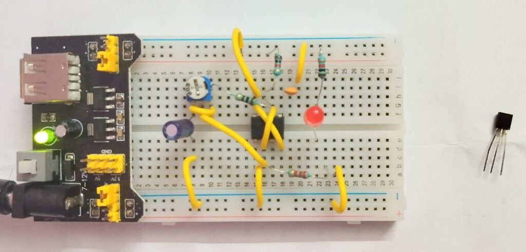
Prototype


Welche Funktion hat der 10K Poti ?
Translated: What is the function of the 10K potentiometer?
Was wird damit eingestellt ?
Translated: What does this set?