Last Updated on March 16, 2024
Construction and Working
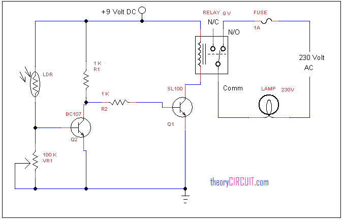
Simple and easy to construct automatic street light circuit is given here, this circuit is constructed by common 5mm LDR (light dependent resistor) and transistor BC 107, switching transistor SL 100.
This switching transistor collector terminal is connected with 9 volt relay terminal, A 230 Volt lamp is connected with relays common terminal and N/O terminal,
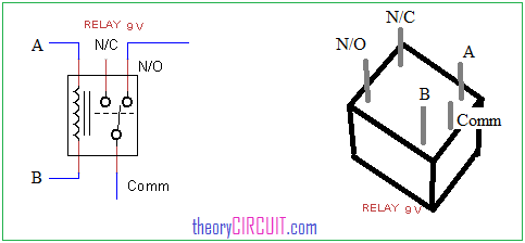
Relay Pinout
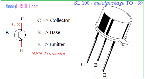
Transistor SL100 Pinout
When the light falls on LDR it gives low resistance to the current flow through it, this supply drives BC107 and connects SL100 transistor base into the ground, when the LDE feels dark condition it gives high resistance to the current flow through it, hence the DC bias from R1 resistor reaches the SL100 transistor base terminal.
So that SL100 receives enough base supply to turn on, by the way relay terminal connected to the ground and becomes electromagnet to attract common lever to N/O contact. When the common terminal completes the lamp circuit through N/O terminal then lamp glows.
Note:- Keep LDR behind the lamp to ensure lamp light is not fall on LDR.
The LDR should observe the sun light only.
Super circuit diagram
Thanks for your Interest 🙂