Last Updated on March 16, 2024
RF remote control circuit designed with 434 MHz ASK (Amplitude shift keying) transmitter and receiver, Here IC HT12E act as encoder and IC HT12D act as decoder, this circuit is constructed with easy available components. This remote gives approximately 150 meter coverage by extending the ariel wire it can be increased up to 200 meters.
This project has two stages that is 1. Transmitter circuit, 2. Receiver circuit first we go with transmitter circuit design.
Transmitter circuit diagram
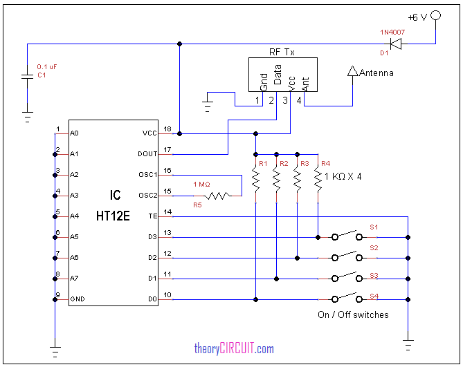
This circuit has three stages they are
- Input switch
- Encoder IC HT12E
- RF transmitter (434 MHz ASK module)
The input switches are connected with encoder ICs data pin, these switches decides the on / off condition by turn on any switch we connect data input pin of encoder ic to the ground, the oscillator pins connected with 1 MΩ resistor because the encoder ic has internal oscillator, Address lines A0 to A7 of encoder is terminated to the ground which is used for address data encoding with unique identity but we don’t need these pins in this project. Output Dout pin 17 is connected with data pin of RF transmitter then the encoded data from IC HT12E is converted as RF signal by ASK transmitter chip and transmitted through air, an ordinary wire is enough to transmit RF signal in short distance by choosing ariel or antenna we can transmit RF signal to long distance.
Receiver circuit diagram
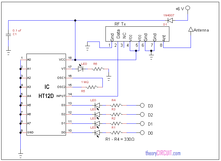
This receiver circuit also has three stages they are
- RF receiver (434 MHz ASK receiver module)
- Decoder IC HT12D
- Output data line
The RF receiver receives RF signal that is transmitted by ASK Transmitter module, and gives output through pin 2, this signal is fed to input pin 14 of decoder IC HT12D, here the Address pin A0 to A7 are terminated to the ground as done in encoder IC, hence we ensure the same address in transmitter and receiver circuit, the decoder IC provides the data output from D3 to D0 pins, this outputs are same as per the switch conditions in transmitter circuit.
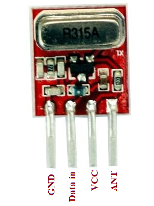
ASK transmitter module
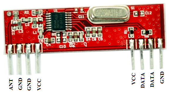
ASK Receiver module
Datasheet
You can get datasheet of IC HT12E here.
You can get datasheet of IC HT12D here.
This is awesome.. Would you show us how to wire these up with h bridge motor drivers?
Hi
Please note that the receiver oscillator (OSC) resistor for the Decoder IC HT12D is 51kOhm and not 1MOhm as indicated.
It is 1M Ohm for the transmitter Encoder IC HT12E OSC resistor
Can we use two ht12d in transmitter and two hd12e in receiver to control four motar two for drive wheels and two for controlling robot arm
According to the datasheet for HT12D the data outputs can sink or source 1.6mA. By my rough calculation the LEDs shown would be trying to sink a current of 10mA to 15mA into D1…4.
Please tell me how much total address you can send and receive data with HT12A, HT12E and HT12D. Maximum number of addresses- How can I use alphabetic letters because the output has only 4 bits. Data is transmitted serially or in parallel. Thank you for your response
Can anyone tell me where to connect the power source in the circuit diagram ?
Can we use two ht12d in transmitter and two hd12e in receiver to control four motar two for drive wheels and two for controlling robot arm