Last Updated on March 16, 2024
This simple easy to construct Li-Ion Battery Charger Circuit is made with IC MCP73831/2 from microchip. This is a miniature single cell full integrated li-ion and li-polymer charge management controller. It is available in tiny package hence most suitable for compact hand held and portable applications.
This MCP73831/2 IC will give constant current and constant voltage for charging battery and also the voltage range and current value can be changed. The output voltage range can be fixed with four available options 4.20V, 4.35V, 4.40V or 4.50V and then current value can be varied by using external resistor connected to the PROG pin.
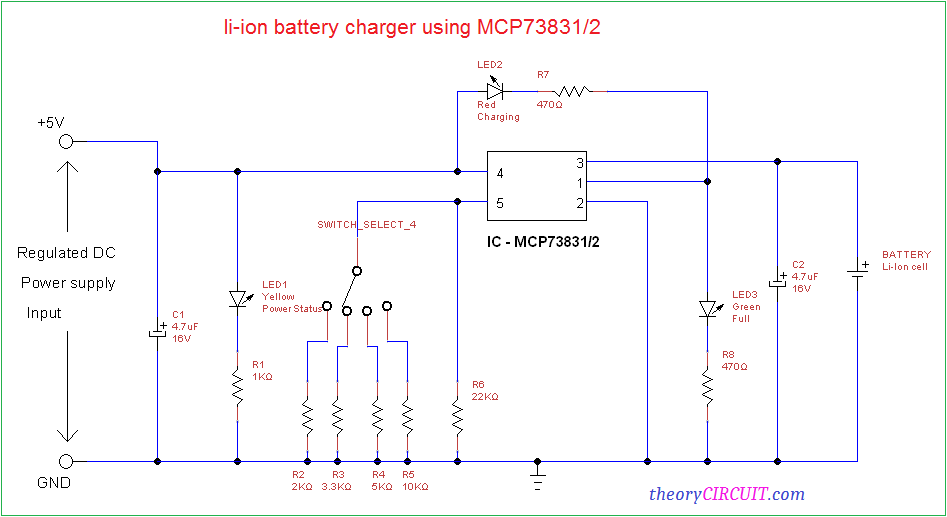
Circuit diagram
Construction and Working
This circuit is designed to charge the Li-Ion battery cell with variable current output, here the four terminal select switch help us to change the charging current. Regulated 5V DC power supply is applied to the charge controllers VDD pin. C1 capacitor performs filter operation and LED1 provides the input power source status, different value resistors (2KΩ, 3.3Ω, 5KΩ and 10KΩ) are connected to the four terminal select swith and then common terminal is connected to PROG pin, by selecting different Resistor we can get different value charging current (15mA to 500mA).
LED2 indicates the battery charging status and LED3 glows if charging battery becomes full. Target Li-Ion battery connected between pin3 and ground.
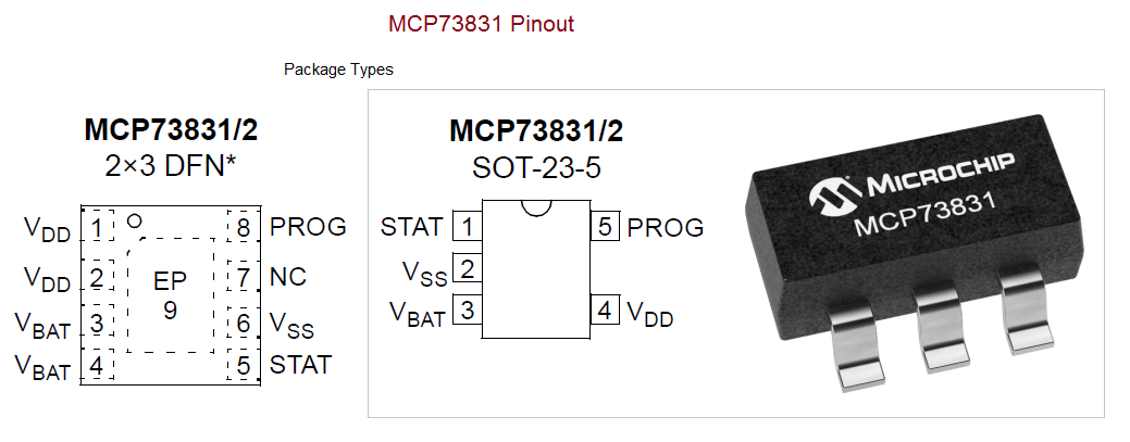
MCP73831/2 Pinout
Note:-
- This circuit gives output current depends on resistor connected to PROG pin(5), Check the output current and battery current rating before apply to charging. .
- Check the battery polarity before connecting to charge pin (VBAT).
- This is untested circuit, Measure all parameters while prototyping.