
Last Updated on March 16, 2024
When we apply Reverse voltage or over voltage to the electronic appliances or electronic components then the result will be damage or burst. To avoid this situation simple Over Voltage and Reverse Voltage Protection Circuit is designed by using few easily available components.
We can use simple single diode for reverse voltage protection to the circuit but when the over voltage or surge spike comes then the load device will get affected. Here Mosfet and Zener diode used as protecting elements.
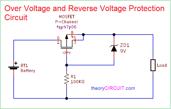
Circuit Diagram
Components Required
- MOSFET P-Channel FQP47P06
- Zener Diode 9V
- Resistor 100KΩ
Circuit Construction & Working
This circuit constructed by using only three elements, First one is P-Channel MOSFET FQP47P06, it is connected between power source and target load and biasing Resistor R1, Zener diode is connected between MOSFET Source and Gate terminal to provide Voltage Regulation at output.
MOSFET FQP47P06
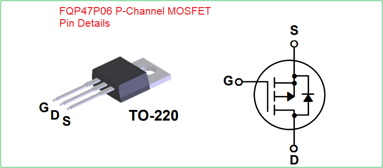
This mosfet can control voltage over 60 Volt, It has three terminals called Gate, Drain and Source. It has high avalanche energy strength (required for reverse voltage protection) and high speed switching character.
When we apply supply to target load at right polarity and voltage then this mosfet allows voltage supply to load and zener diode just acts as forward biased diode. When reverse voltage occurs then MOSFET p-channel holes will flow towards negative supply and creates barrier between Drain and source terminal hence there is no supply flow to the load. If the right polarity supply applied but the voltage increases beyond 9V then zener breakdown occurs in zener diode and regulates the voltage to 9V and allows to the target load.
When we use single PN junction diode as reverse voltage protector then high reverse voltage or high forward current will burst the diode. For sensitive target load this simple Over Voltage and Reverse Voltage Protection Circuit using mosfet will be the right choice.
This is just a simple reverse polarity protection circuit, it will protect the circuit against over voltage!
The MosFET body diode will conduct always independetly of the zener.
The zener is just protecting the the MosFET gate-source.
sorry I want to say, it will not protect against over voltage
This circuit still passes 18v. So it DOES NOT protect against over voltage.
ZD1 9V protects gate junction and regulates the gate source voltage and stop it from reaching the max with respect to input voltage. so its not protect against over voltage.
This circuit only protects agains reverse polarity
Thanks for share.
Thanks for your appreciation