
Last Updated on March 16, 2024
Passive Infra Red motion sensor mostly used in security based designs, and due to its robust operation and low cost simple security circuits also includes PIR sensor in design. The PIR motion detector circuit designed with Relay to turn On electric bulb when ever the PIR sensor detects motion.
This circuit can be implemented any where like staircase or front gate etc., and when the PIR sensor detects person movement it will triggers Relay and makes electric bulb glow.
Circuit Diagram
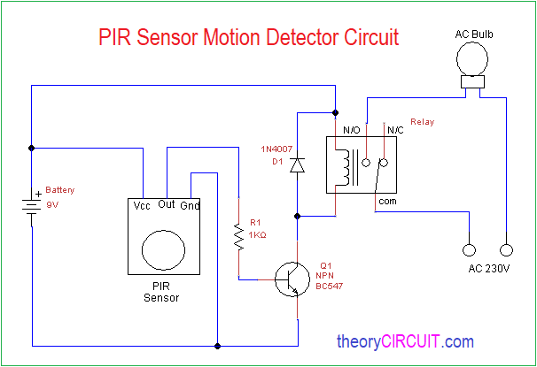
Components Required
- PIR Sensor
- 5V Relay
- Transistor BC547
- Diode 1N4007
- Resistor 1KΩ
- 9V Battery
- Electric Bulb
Construction & Working
This PIR sensor has only three terminals and gives logical output when detects the motion, Hence it can be used in stand alone alarm, security circuits or light automation circuits.
The PIR motion detection circuit constructed with few easily available components, you can use Relay breakout board also, The PIR sensor Output pin is connected to the switching transistor BC547 base and Relay coil is connected to the switching transistor collector terminal another end of Relay coil is connected to the positive supply, the electric bulb is connected with N/O (Normally Open) terminal, when the Relay turn On then common pin makes contact with N/O pin and then bulb starts to glow.
Note:- High Volt AC supply are dangerous Handle with extreme care.
Can I ask the voltage of the electric bulb?
220-230 VAC serial to relay’s normally open (N/O) contact
Can we change this circuit into 3.7 VDC (18650 Lion batt) omitting the relay and putting a suitable LED?
Hi Umit
Most PIR Sensor can operate with 3.7 VDC even though you can check the PIR sensor Operating Voltage and yes you can use 18650 Lion batt and LED instead of Relay (put Resistor before LED)