Last Updated on August 8, 2025
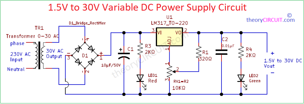
Simple Variable LM317 voltage regulator circuit using few easily available components has been designed and tested in this article as follows. We know LM317 is a popular adjustable positive voltage regulator with capability of delivering 1.5A output current to the load over an output-voltage range of 1.25 V to 37 V. LM317 has only three terminals and gives variable regulated output.
LM317 IC includes current limiting, thermal overload protection, and safe operating area protection. Overload protection remains functional even if the ADJUST terminal is disconnected. This IC comes in different package size, depends on circuit design and thermal consideration we can choose LM317.
LM317 Pin Diagram
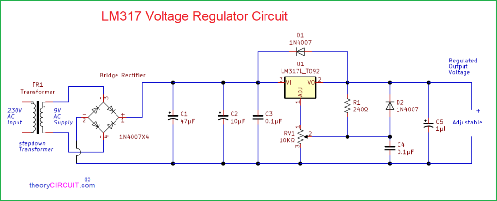
Circuit Diagram
Components Required
- Step down transformer 0-9V 1 amps
- Bridge Rectifier module or 1N4007X4
- IC LM317
- Variable Resistor 10KΩ
- Resistor 240Ω
- Diode 1N4007 = 2
- Capacitor 47uF, 10uF, 1uF each one
- Capacitor 0.1uF = 2
Construction & Working
Here we designed this variable power supply unit to give 1.5V to 9V regulated output voltage, you can apply your desired input supply upto 37V. This circuit design starts with step down transformer and then Bridge Rectifier module to rectify AC supply into DC supply. Then filter capacitors C1, C2 and C3 are removes AC ripples and distortions. Regulator IC LM317 adjust pin connected with variable Resistor and output through feedback resistor R1. At the output diode D2 provides reverse voltage protection.
LM317 Regulates input DC supply from Rectifier and takes feedback from output through D1 and adjustable pin takes feedback voltage and current through variable Resistor and R1 resistor. Hence the output at the load appears constant and output voltage range can be adjusted by RV1. Use heatsink when you expect to obtain output voltage beyond 15V.
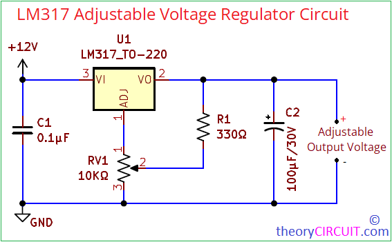
Updated Version Of Variable LM317 voltage regulator circuit
Here is the Simple LM317 Adjustable Voltage Regulator circuit without any fancy components.
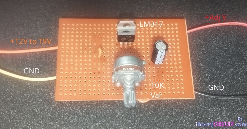
LM317 Adjustable Voltage Regulator on Veroboard


