Last Updated on March 16, 2024
Short circuit is a common problem in every circuit and it may occur any time during operation. When the short circuit occurs it may damage some sensitive electronic components and long time short circuit may cause severe damage to the circuit and also power source. Here simple Short-Circuit Protection Circuit designed to give audible and visual alert during the short circuit problem
You can connect any relay switch to direct the circuit while short circuit occurs. For testing purpose we have used Buzzer and LED as a output actuator.
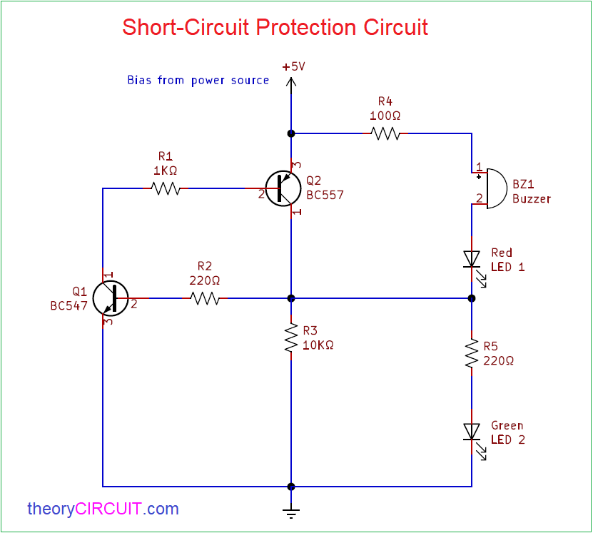
Circuit diagram
Components Required
- Transistor BC557 (PNP)
- Transistor BC547 (NPN)
- Buzzer
- LED green, red each one
- Resistor 220Ω = 2
- Resistors 100Ω, 1KΩ, 10KΩ each one
Circuit Construction & Working
Two transistors are connected in anti parallel and output device buzzer, LED (Red) connected between Q2 Emitter and collector terminals followed by LED (Green). This whole circuit is connected with the power supply source that is applied to the target load circuit.
When there is no short circuit means the green LED will glow, if there is any short time or long time short circuit occurs then red LED will glow and also buzzer will make noise.
Operation of this circuit is simple, consider Q1 and Q2 transistors as a switch. When normal power supply flow Q2 in ON condition and Q1 OFF condition so the Green LED gets bias and glow. When short circuit occurs Q2 will be in OFF condition and Q1 will be in ON condition so the buzzer and Red LED will get bias and gives alert.