Last Updated on October 2, 2025
If you want to built simple audio amplifier without messy components then you can construct simple single transistor audio amplifier circuit using BC547 and Resistor, Capacitor. This circuit can drive 8 ohm loud speaker and produce considerable sound. Apply 9 Volt DC supply for better result.
Single BC547 (NPN) Transistor based audio amplifier circuit has been constructed as a experiment but the output response was amazing. This compact yet powerful audio amplifier circuit leads designers to explore minimalist approaches. Just one transistor is enough for you to design immediate and instant audio amplifier or pre amplifier with few external Resistor and Capacitor. Try it and share your experience in comment section below.
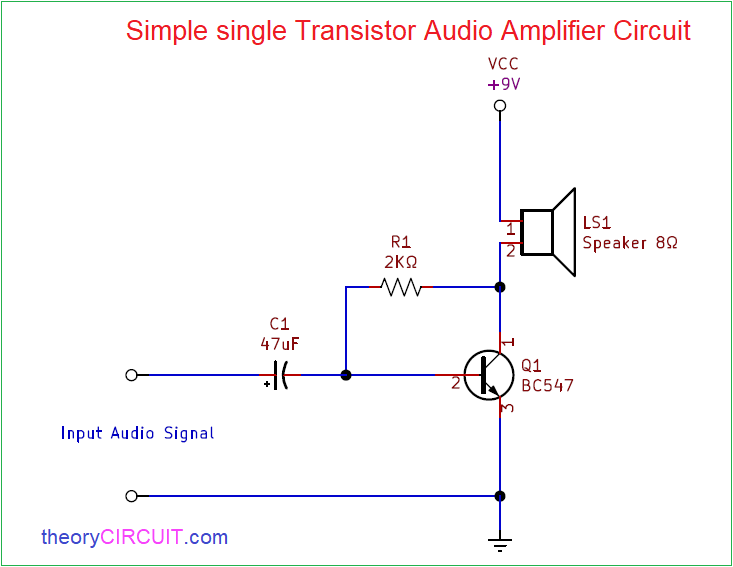
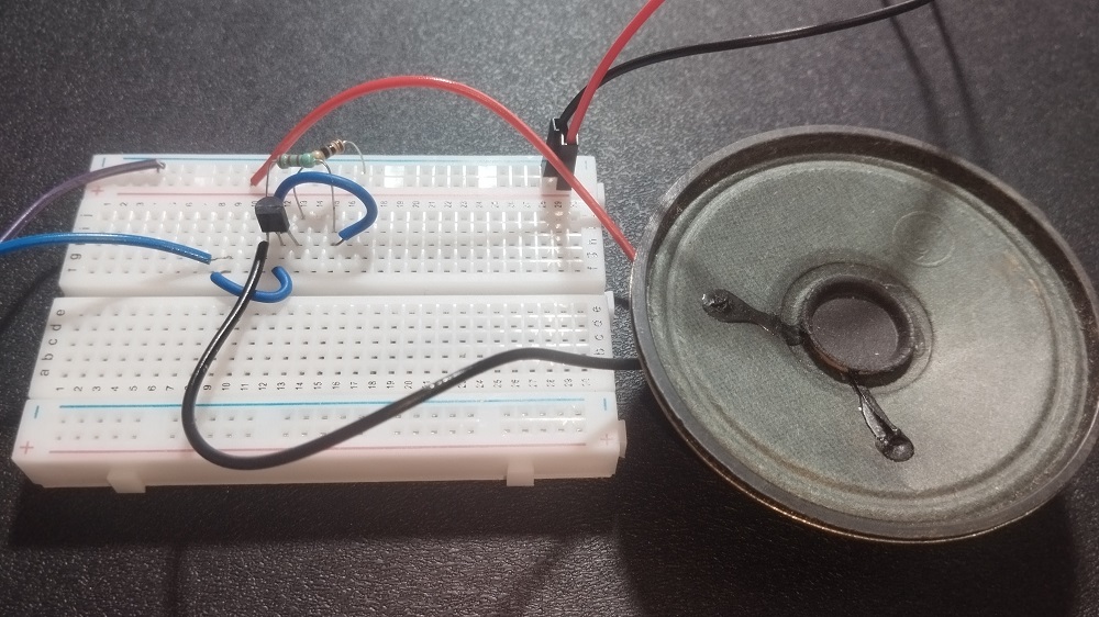
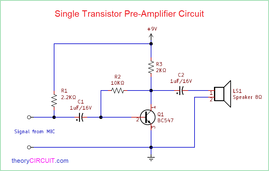
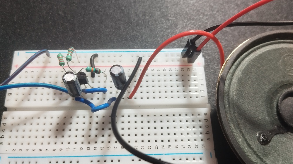
Two types of single transistor audio amplifier circuit designed with BC 547 transistor, here first one is for to amplify direct audio signal and another one is for to amplify audio signal from condenser MIC as a preamplifier.
Circuit Diagram
Prototype
Testing
PreAmplifier
Prototype
Testing (with speaker)
Components Required
- Transistor BC 547 (NPN) =2
- Resistor 2KΩ = 2
- Resistor 10KΩ, 2.2KΩ each one
- Electrolytic Capacitor 47µF/16V
- Electrolytic Capacitor 1µF/16V = 2
- Loud Speaker
- 9V Battery
Construction & Working
To construct Amplifier circuit start with Transistor BC 547 and Connect proper bias to Collector, Base and Emitter terminals, For the first circuit Loud speaker is directly connected to the transistor collector terminal and for Preamplifier circuit speaker connected through coupling capacitor C2.
Input Audio signal for the first circuit is applied to the BC 547 base through Capacitor C1 (47µF) and Collector coupled Resistor R1 hence the enough Audio signal and bias above cutoff voltage is constantly present at Base terminal of BC 547 and amplify the input signal near to peak Vcc.
Input Audio signal for the second circuit is applied from the Condenser MIC and it may raw electric audio signal with distortion and noise in order to improve the audio signal we need to filter and amplify the input signal. To give strength to the MIC signal R1 resistor is connected at the input to Vcc and C1 capacitor is responsible for removing distortion and coupling audio signal to transistor BC 547 Base. R2 acts as a Collector coupling Resistor then output audio signal is received from Collector terminal and applied to Loud Speaker through C2 capacitor. By applying Bias above cutoff to transistor we can take no phase shift audio signal.


1.input and output voltages should have been indicated
2.a variable resistor inthe input line is absent
HOW MANY WATTS CNA WE EXPECT FROM THIS CIRCUIT?
first circuit faulty transistor collector pin short circuit ?
Works well, any way to make louder?
To make it louder we need to add transistor stages and increase bias voltage and current.
You used 10 watt speaker?
Hi,
Yes, you can use 10 Watt speaker.
Pls can we substitute the bc547 transistor
just use any audio transistor
Will increasing the voltage from 9v to 12v increase the volume level, or would you have to recalculate the resistor values to compensate. I want to use a TIP120 Darlington transistor for an amplifier.
Hi Marty W
We would say that increasing the supply voltage from 9V to 12V can potentially increase the volume level of your amplifier, but it may also require recalculation of resistor values to ensure that the amplifier operates safely and optimally.
The TIP120 Darlington transistor is a type of bipolar junction transistor (BJT) that can be used in amplifier circuits. In a simple common-emitter amplifier circuit using a TIP120, increasing the supply voltage can cause an increase in the collector current, which can in turn increase the output signal amplitude and potentially the volume level. However, this increase in voltage can also cause the transistor to exceed its maximum voltage rating, which can damage the transistor and cause the circuit to fail.
To ensure that the TIP120 and the other components in the amplifier circuit are not damaged and that the circuit operates optimally, it is important to recalculate the values of resistors and other components based on the new supply voltage. In particular, the biasing resistors and the load resistor should be chosen or adjusted to provide the correct DC biasing and signal amplification for the new voltage level.
Overall, increasing the voltage in an amplifier circuit can have both positive and negative effects on the circuit performance, and careful consideration and calculation are required to ensure safe and optimal operation.
How can I get base circuit.
Hi Koranteng Daniel,
Refer Datasheet of your Transistor.
How to connect Trasmitter in the first circuit?
What type of Transmitter? We can’t understand!
What is the role of capacitor and resistor in the first circuit? Is it hi pass filter?
Hi Karol,
There are two reasons, First one is, it blocks any DC voltage that might be present at the input, ensuring that only the AC audio signal passes through. This is crucial to prevent any DC offset from affecting the amplifier’s operation.
Second one, the capacitor helps in coupling the AC audio signal into the amplifier. It also provides a high pass filter effect, blocking low frequency signals and allowing only the audio frequencies to pass to another stage. This is useful for eliminating any potential low frequency interference or unwanted DC components.
how about 8 ohm 0.5 watt speaker?
Thank you for providing this exercise! I am using this to learn the basics of sound amplification. I have built an Arduino project that uses an Mini DFPlayer (https://wiki.dfrobot.com/DFPlayer_Mini_SKU_DFR0299#Connection_Diagram). I have built your pre-amp version using SMD ceramic non-polarized caps (which I have on-hand), and found that the output is much lower than the output to an 8 ohm speaker connected directly to DFPlayer’s SPK_1, and SPK_2 . I have ordered polarized electrolytic caps, to see if that’s why the output is so low. While waiting for the caps, can you please explain which DFPlayer connections I need to use as “signal from mic”? I don’t really understand the reason the DFPlayer provides two outputs. But, I do know that when I connect both to the speaker, the direct sound is much louder than if I connect either SPK_1 & GND, or SPK_2 & GND.
Thanks, I appreciate your help.
Hi Bob, Just try the following
1. Use DAC_L or DAC_R for line-level audio signals to your pre-amp.
2. Use polarized electrolytic capacitors for coupling audio signals in pre-amp circuits to ensure proper signal transfer, especially for low
frequencies.
3. To get the full audio output for speakers, connect both SPK_1 and SPK_2 to the speaker, rather than one speaker pin and GND.
Sorry, I’m a little confused about item 3. If I connect DAC_L & GND or DAC_R & GND as input to the pre-amp, shouldn’t I connect my speaker to the the pre-amp’s output, as LS1 is shown? I did do that, but the volume is very low.
Transistor overheated and made a bad smell. I used the right transistor BC547 and used 3 of them. Checked my wiring twice and my power supply but they all still overheated
I had the same problem, their schematic must be missing some part or is just plain wrong.
I built the “single transistor” sample circuit pictured at the top of this article. Triple checked my work to be exactly as the schematic shows, and BOTH times my BC547 smoked after less than 30 sec of operation. The schematic must be missing or wrong. To anyone reading, do not build the first schematic as it is shown or you’ll just throw away your parts. I am now out the last of my BC547s and my project is now stuck in limbo while I order more.