Last Updated on March 16, 2024
LEDs have revolutionized the lighting we use in our day to day life and electronics industry, due to their efficiency and convenience. In this tutorial, we will reveal the magic behind the stunning effect: the dim LED. Think of it as a slow, gradual transition between light and dark, this dramatic effect is achieved through fading, transparent LED circuitry. What makes this project more interesting is the use of an obsolete 555 timer IC, a Timer IC you can see anywhere in electronics circuit. Simple Fading LED Circuit using 555 Timer requires only few components and you can construct this circuit within minutes.
Timer IC 555
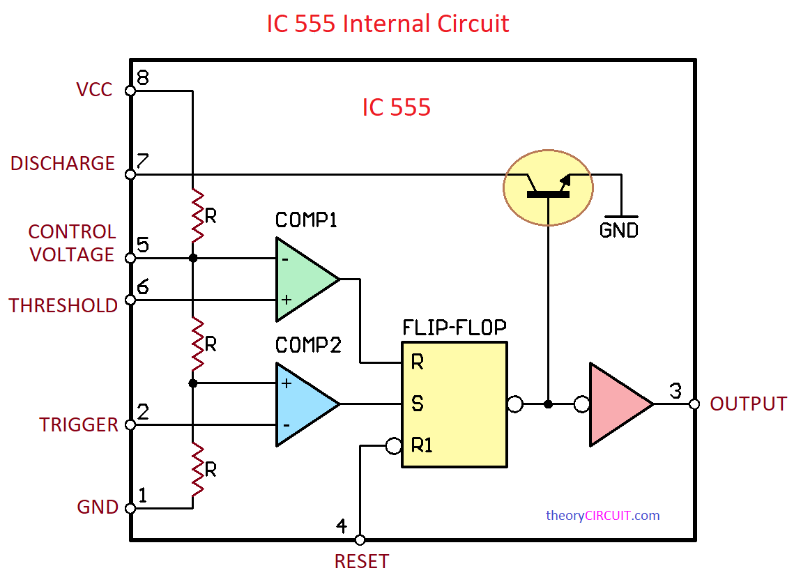
We have talked much about Timer IC 555 even though that is not enough because the ability of Timer 555 is more and it deserves it. Simple quick note about 555, In its basic form 555 timer consists of two voltage comparators, an SR flip-flop, a discharge transistor, and a resistor divider network. The voltage comparators monitor the voltage levels at the threshold (pin 6) and trigger (pin 2) inputs, comparing them to a reference voltage derived from the resistor divider network. Here Control Voltage Input pin 5 of the IC is an important input that allows external voltage control of the threshold and trigger levels. When the voltage at the trigger pin falls below 1/3 of the supply voltage, the output flips, setting the flip-flop and turning ON the discharge transistor.
Conversely, when the voltage at the threshold pin rises above 2/3 of the supply voltage, the flip-flop is reset, and the discharge transistor turns OFF. This configuration allows the 555 timer to operate in various modes, including Astable, Monostable, and Bistable, making it an essential building block in electronic circuits, timers, pulse generators, and oscillators. In our fading LED circuit, we will use the 555 timer in an Astable mode to create the fading effect.
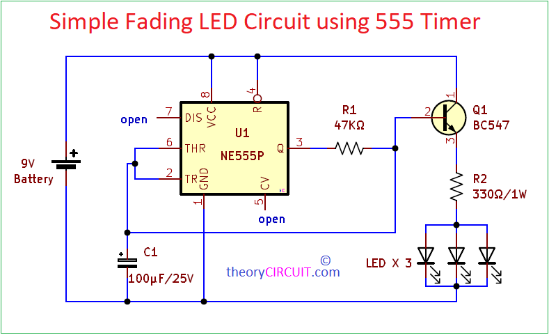
Circuit Diagram
Components List
- Timer IC NE555P
- Transistor BC547 NPN
- LEDs
- Capacitor 100μF/25V
- Resistor 47KΩ, 330Ω
- Battery 9V
Construction & Working
In this circuit Positive supply is applied to Pin 8 (VCC) and Pin 4 (RESET), by connecting Reset pin to VCC prevents unwanted reset, and Negative or ground is applied to Pin 1 (GROUND), Pin 5 (Control Voltage) is not used in this configuration and is usually grounded with 0.1μF capacitor, this pin can be used to precise the voltage in divider network. Pins 2 and 6 (Trigger and Threshold) are connected together for creating a stable trigger level, these two pins connected with timing capacitor C1. Pin 7 (DISCHARGE) is not used and kept in open condition to avoid toggle ON and OFF. Pin 3 (OUTPUT ) is connected with Transistor base and Charging capacitor through R1 Resistor. LEDs are connected in the Emitter pin of Q1 through R2.
Here the 47KΩ Resistor (R1) and 100μF (C1) capacitor create a charging an discharging cycle, and acts as timing elements for Timer IC 555. At the output Transistor base gets gradual rising and gradual falling voltage levels and acts as gradual ON/OFF Switch then controls the current flowing through the LEDs. As the capacitor charges and discharges, the voltage at the base of the transistor varies. This variation in voltage causes the LED to fade in and out gradually, creating the fading effect.
BC547 Pinout
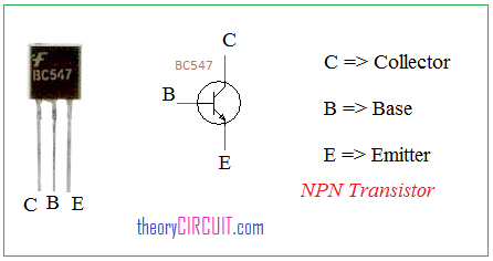
The BC547 is a commonly used NPN bipolar junction transistor (BJT) in electronic circuits. As an essential semiconductor device, it serves various purposes in amplification and switching applications. With a maximum current rating of 100 mA and a voltage rating of 45V, the BC547 is suitable for low-power amplification tasks. Its typical current gain (hFE) falls within the range of 110 to 800, making it ideal for small-signal amplification. This transistor is widely utilized in audio amplification, signal processing, and oscillator circuits due to its reliability and affordability. Its versatility, coupled with its availability in TO-92 packaging. Here this transistor employed as Switch.
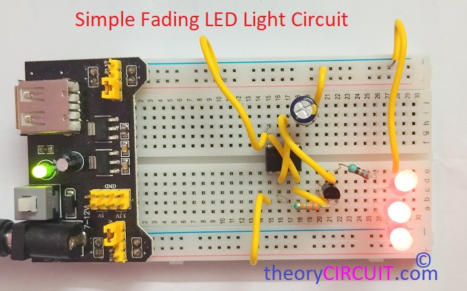
Prototype