Last Updated on January 27, 2025
In today’s world, We hold different types of portable electronic devices and gadgets and many of those are comes with rechargeable battery. Even though we can charge it through household electric supply try the following fun way, A solar powered USB charger is a great way to harness renewable energy to charge devices on the go. You can use this circuit for many useful applications like emergency light, garden lighting, pond water pump etc.., (Remember to optimize components depends on your applications).
Here you can learn to build, DIY Solar Powered USB Charger circuit for Li-Ion Battery (mostly 18650) and you can use the output voltage from this circuit to your desired applications. Charger module used here provides two option to input power one is through micro USB and another one through +, – terminals. Here we use Solar panel to power this module. It capture sunlight and convert it into usable electrical energy.
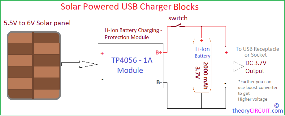
Block Diagram
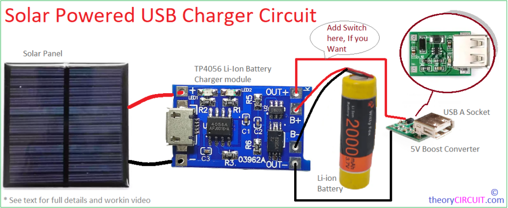
Circuit Diagram
Use one diode (1N4007) in positive line between (Anode-Cathode) Solar panel to TP4056 module for polarity protection.
Components Required
- Solar Panel 6V (100mA to 500mA)
- TP4056 Li-Ion Battery Charger Module
- Switch
- Li-Ion Battery 3.7V (2000mA)
- USB A Socket (Boost Converter if you need)
Working Video
Construction & Working
Starting with solar panel, it will give 6V – 200mA output with full expose to sunlight, Output voltage and current may vary depends on the intensity of sun light. This panel comes with two terminals and mostly denoted with ‘+’ and ‘-‘ signs, if not use the multimeter to identify the polarity before connecting it with charger module.
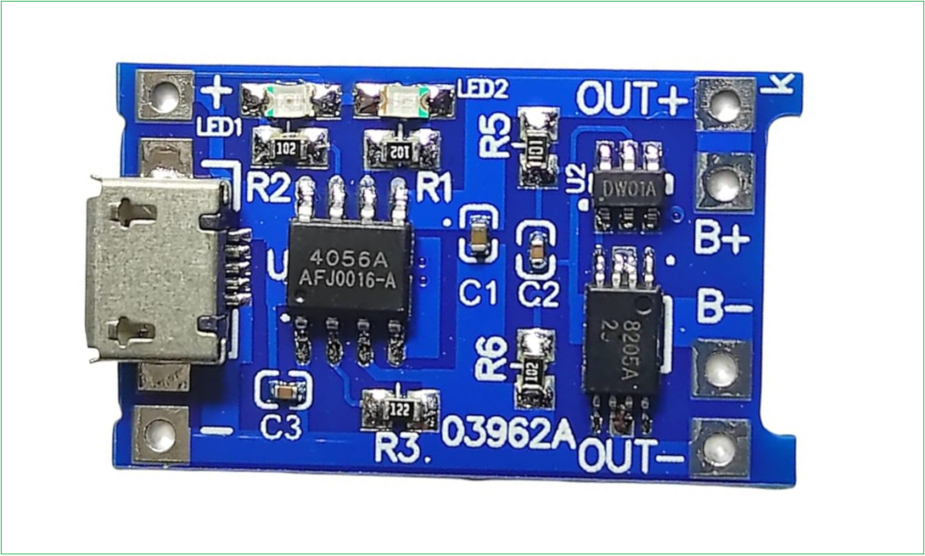
TP4056 Lithium Ion Battery Charging Module is the next important part of this circuit, you may aware that it is widely used for charging single cell Li-Ion batteries. It provides battery protection functions such as overcharge, over discharge, and short-circuit protection.
This module uses IC TP4056, which is a complete constant-current/constant-voltage linear charger for single cell li-ion batteries. It comes with SOP package and requires few external components to work. So it makes this IC suitable for poratble electronics. No blocking diode is required due to the internal PMOSFET architecture and have prevent to negative Charge Current Circuit.
TP4056 IC charge voltage is fixed at 4.2V, and the charge current can be programmed externally with a single resistor (This module uses 1.2KΩ Resistor and the Charge current fixed at 1000mA). The TP4056 automatically terminates the charge cycle when the charge current drops to 1/10th the programmed value after the final float voltage is reached.
DW01A IC in the module is the single cell li-ion battery protection IC with dual MOSFET. This IC monitors the battery voltage and prevents over discharge by disconnecting the load when the voltage drops below 2.5V, DW01A controls FS8205A Dual N Channel Power MOSFET in TSSOP-8 package.
Here we used witty fox 3.7V 2000mAh Li-ion Battery and connected its positive terminal to B+ and Negative terminal to B- of TP4056 module. With the power from solar panel this battery gets charge and discharge to the load when there is no input power to tp4056 module, use switch to disconnect load. LED1 Indicates charging in progress, LED2 Indicates charging completed (battery fully charged).


