
Last Updated on March 16, 2024

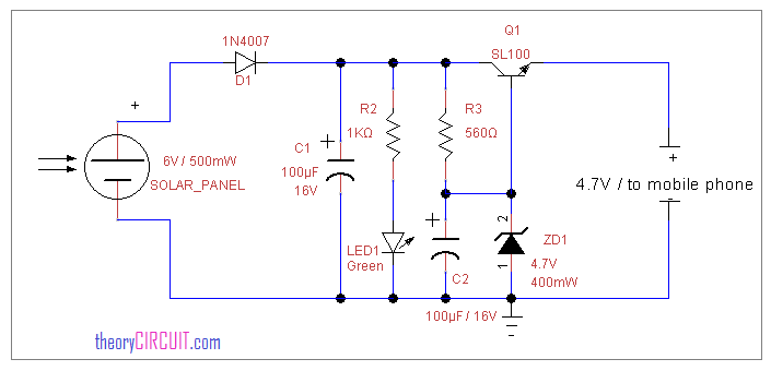
This circuit helps you to charge your mobile phone battery and also some rechargeable battery with solar energy, before trying this circuit take extra care in battery polarity and current rating, if anything goes wrong the battery might explode. ZD1 Zener diode used as a voltage regulator, you can use up to 5.2V Zener diode for your application. SL100 is seems like obsolete component, Use 2N2222 NPN Transistor.
Circuit Construction
Components List
- 6V 500 mA Solar Panel
- Diode 1N4007
- Capacitor 100μF/16V = 2
- Resistor 1KΩ, 560Ω
- LED
- 4.7V Zener diode
- Transistor SL100 or 2N2222 NPN
Here the circuit utilize 6V/500 mW solar panel, and then single PN junction diode 1N4007 connected towards positive line of solar panel this will avoid reverse polarity. An green LED connected across the solar panel supply line after the C1 capacitor which provides status of supply output from solar panel.
You can remove R2 and LED if you don’t need light indicator. SL100 transistor with 4.7V/400mW zener diode provides regulated supply from solar voltage. Choose the zener diode specification according to your need. Here the zener diode connected in base of SL100 transistor with reverse biased polarity.
Working
Expose the solar panel in sunlight, that solar energy will be converted as voltage by the photovoltaic device (solar panel cell), then the green LED glows here the intensity of this LED varies depends on the voltage produced by the solar panel. The zener diode reduce and regulates voltage and the SL100 transistor drives output voltage.
Test Points
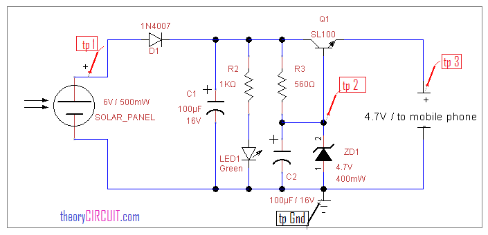
- tp GND – test point common ground
- tp 1 – To check solar panel voltage – 5V to 6V
- tp 2 – To check Zener voltage – 4V to 4.7V
- tp 3 – To check output – 4.5V – 4.7V
Before trying this circuit take extra care in battery polarity and current rating, if anything goes wrong the battery might explode.
what is SL100 transistor?
I cant find it in any store !!
I have used 2N2222A to replace SL100 without any problem. Good luck.
Please tell me how to connect sl/100 transistor in solar mobile charger
why we used two capacitors and R3 .pls tell me
I believe C1 is there to smooth out changes in voltage from the solar panel. C1 will charge up to the maximum voltage produced by the solar panel. C2 will help steady the 4.7 voltage across the zener. R3 is to take the voltage drop left over from the zener diode.
So the voltage across R3 is:
VR3 = 6V – 4.7V (Kirchhoff’s Voltage Law)
VR3 = 1.3 Volts
So without R3 this 1.3 Volts would be dropped across the internal resistance the solar panel.
Plz help me to do this circuit … Replay me again
Solar panel with how much current is required to do this project . solar panel may produce different amount of currents.so i request you to answer this question .
How do we do this circuit in multisim? How can we get a solar panel with the required characteristics, as the solar panel symbol is not available in multisim
Can i use 100uf /25 v capacitor instead of 100uf/16 v.?
Plzz rply i take this as ma project
OK, so Im doing a GCSE and i am making this for my sustainability project and i have no idea what this stuff is and how to connect it all together