
Last Updated on March 16, 2024
Regulated power supplies are essential for every electronic circuits, prototypes and element testing, imagine you are in a situation that you don’t have access to Regulated power Supply, here we come to the rescue, You can easily construct USB based Zener diode Voltage regulator circuit with components you have in your desk. The following circuit gives regulated DC power supply from USB port by using Zener diode as a regulating component.
Before jumping into the Circuits, Lets remember What is Zener Diode? and How it is acts as Voltage Regulator? from our kindergarten class.., A Zener diode is a semiconductor device that allows current to flow in the reverse direction when a specific breakdown voltage (known as the Zener voltage or Zener breakdown voltage) is reached. This unique characteristic makes Zener diodes ideal for voltage regulation applications.
Zener Diode
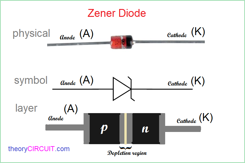
Now you are looking at Two terminal Zener diode Physical appearance, symbol and Internal structure. This diode acts as Normal PN Junction diode in forward bias that is Positive supply to Anode and Negative Supply to cathode. When we apply reverse bias that is +Ve to Cathode (K) and -Ve to Anode (A), and increasing bias up to Zener breakdown voltage level, then Zener diode conducts very little current (in μA), After the bias reaches Zener breakdown voltage then Zener diode Conducts current to its maximum level with constant Voltage. All Zener diode comes with this breakdown voltage level that is known as regulating voltage level.
VI Characteristics of Zener Diode
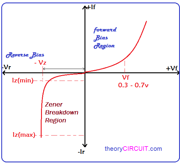
In this graph X axis represents Voltage and Y axis represents Current.
Circuit Diagram
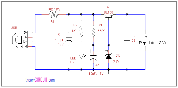
USB port (see more about USB) gives DC bias from pin 1 and pin 4, that power supply regulated by using Zener diode, by choosing different voltage Zener diode we can get different level of regulated DC voltage. when we use USB power source, we can use up to 5V Zener diode as maximum level. (see zener diode tutorial). keep in mind that Voltage wanted to be regulated must be greater than Zener diode breakdown voltage.
The LED connected with R2 resistor indicates the power supply presence, the transistor SL100 drives output supply and the resistor R1 provides protection to the USB port.
Get SL100 transistor data sheet here, You can use CL100 NPN or BC547 NPN transistor instead of SL100.
The Following Zener diodes can be used in this Circuit.
| 1/2W | 0.5W | 0.5W | 1W | 1W |
|---|---|---|---|---|
| Voltage | DO-35 | LL34 | DO-41 | LL41 |
| 2V0 | BZX55C2V0 | ZMM2V0 | ||
| 2V2 | BZX55C2V2 | ZMM2V2 | ||
| 2V4 | BZX55C2V4 | ZMM2V4 | ||
| 2V7 | BZX55C2V7 | ZMM2V7 | ||
| 3V0 | BZX55C3V0 | ZMM3V0 | 1N4727A | ZM4727A |
| 3V3 | BZX55C3V3 | ZMM3V3 | 1N4728A | ZM4728A |
| 3V6 | BZX55C3V6 | ZMM3V6 | 1N4729A | ZM4729A |
| 3V9 | BZX55C3V9 | ZMM3V9 | 1N4730A | ZM4730A |
| 4V3 | BZX55C4V3 | ZMM4V3 | 1N4731A | ZM4731A |
| 4V7 | BZX55C4V7 | ZMM4V7 | 1N4732A | ZM4732A |