
Last Updated on March 16, 2024
Simple Step down Voltage Regulator Circuit designed by using IC LM2678. This Circuit takes 8 volt to 40 volt as input and gives 5 volt / 5 Amps Regulated DC as output. IC LM2678 from Texas Instruments is monolithic Integrated circuit which provide all of the active functions for Step down (buck) switching Regulator.
IC LM2678 is capable of driving up to 5A Load with load Regulation characteristics. These IC series Consists of fixed output Voltages 3.3V, 5V, 12V and Adjustable output versions.
Circuit Diagram

Components Required (BOM)
| 1 | C1, C2, C3 | 15 µF | CP_Radial_D4.0mm_P1.50mm | 3 | ||
| 2 | C6, C7 | 180 µF | CP_Radial_D4.0mm_P1.50mm | 2 | ||
| 3 | C4 | 0.47 µF | C_Disc_D3.0mm_W1.6mm_P2.50mm | 1 | ||
| 4 | C5 | 0.01 µF | C_Disc_D3.0mm_W1.6mm_P2.50mm | 1 | ||
| 5 | L1 | INDUCTOR | L_Radial_D10.0mm_P5.00mm_Fastron_07M | 1 | ||
| 6 | D1 | 1N5821 | D_DO-201AD_P15.24mm_Horizontal | 1 | ||
| 7 | U1 | LM2678 | TO-220-7_P2.54×3.7mm_StaggerOdd_Lead3.8mm_Vertical | 1 | ||
| 8 | J1, J2 | Screw_Terminal_01x02 | JWT_A3963_1x02_P3.96mm_Vertical | 2 |
Construction & Working
In this Step down voltage Regulator circuit, we have taken fixed output IC that is 5V Output LM2678. This IC has internal 5 Volt Regulator, 260KHz Oscillator, and thermal shutdown block.
Input DC Voltage 8 V to 40 V is directly applied to the Vin Pin through filter capacitors. Here ON/OFF’ control pin is kept in open for ICs continuous operation. If it is used as battery charger circuit with auto cut off option we can use this pin to shutdown the IC. Switch output is applied to the Inductor and capacitors at the end we can take 5V Regulated output with maximum 5 Amps load current.
IC LM2678 needs only few components for its full operation. This IC consumes 50-μA standby current when switch off condition and this is very low when compared to its peers.
Printed Circuit Board (PCB)
Step Down Voltage Regulator Circuit Gerber files.
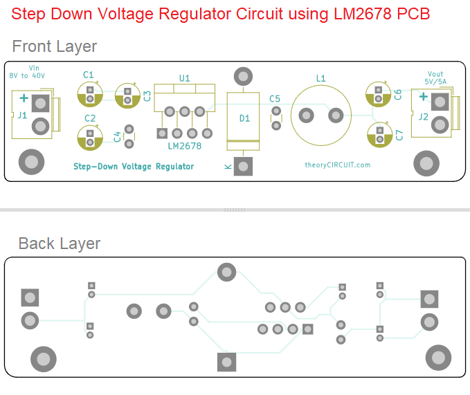
Interactive Board Viewer

