
Last Updated on March 16, 2024
For Testing Electronic circuits or components and for Bench Power Supply we need Adjustable Voltage Regulator to provide Voltage between 0.7V to maximum 30V or more. Here Simple Adjustable Voltage Regulator 30V Circuit using LM723 designed with minimum external components.
IC LM723 from Texas Instruments is a voltage regulator designed primarily for series regulator applications. It can supply output current in excess of 10A possible by adding external transistors (refer datasheet). This IC consumes low standby current and these ICs are used in wide range of applications such as a shunt Regulator, Current regulator or a temperature controller.
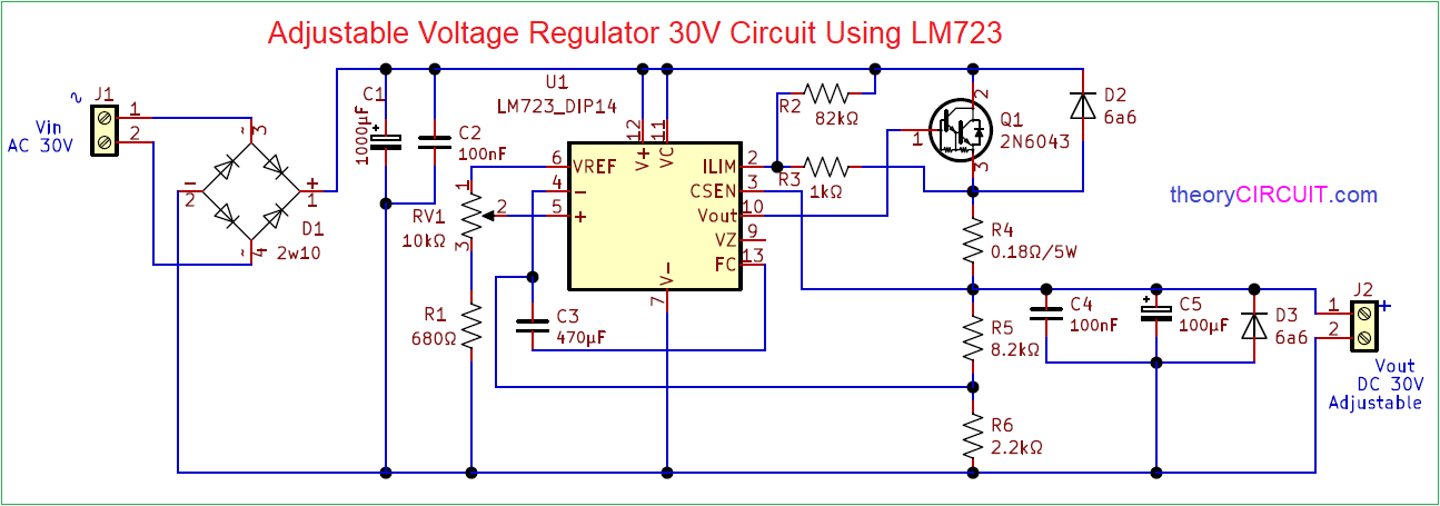
Circuit Diagram
Components Required (BOM)
| 1 | C1 | 1000µF | CP_Radial_D4.0mm_P1.50mm | 1 | ||
| 2 | C3 | 470µF | CP_Radial_D4.0mm_P1.50mm | 1 | ||
| 3 | C4 | 100nF | CP_Radial_D4.0mm_P1.50mm | 1 | ||
| 4 | C5 | 100µF | CP_Radial_D4.0mm_P1.50mm | 1 | ||
| 5 | C2 | 100nF | C_Disc_D3.0mm_W1.6mm_P2.50mm | 1 | ||
| 6 | R1 | 680Ω | R_Axial_DIN0204_L3.6mm_D1.6mm_P7.62mm_Horizontal | 1 | ||
| 7 | R2 | 82kΩ | R_Axial_DIN0204_L3.6mm_D1.6mm_P7.62mm_Horizontal | 1 | ||
| 8 | R3 | 1kΩ | R_Axial_DIN0204_L3.6mm_D1.6mm_P7.62mm_Horizontal | 1 | ||
| 9 | R5 | 8.2kΩ | R_Axial_DIN0204_L3.6mm_D1.6mm_P7.62mm_Horizontal | 1 | ||
| 10 | R6 | 2.2kΩ | R_Axial_DIN0204_L3.6mm_D1.6mm_P7.62mm_Horizontal | 1 | ||
| 11 | R4 | 0.18Ω/5W | R_Axial_Power_L20.0mm_W6.4mm_P22.40mm | 1 | ||
| 12 | D2, D3 | 6a6 | D_DO-15_P10.16mm_Horizontal | 2 | ||
| 13 | D1 | 2W10 | Diode_Bridge_Round_D9.0mm | 1 | ||
| 14 | U1 | LM723_DIP14 | DIP-14_W7.62mm | 1 | ||
| 15 | RV1 | 10kΩ | Potentiometer_Bourns_3266Y_Vertical | 1 | ||
| 16 | Q1 | 2N6043 | TO-220-3_Vertical | 1 | ||
| 17 | J1, J2 | Screw_Terminal_01x02 | JWT_A3963_1x02_P3.96mm_Vertical | 2 |
Construction & Working
IC LM723 Comes in different packages we can choose any that suits our application. 0-30V Adjustable Voltage Regulator Circuit here starts with Bridge Rectifier and 30V AC is applied directly to the Bridge Rectifier module.
Rectified DC supply from bridge Rectifier filtered with the help of C1, C2 Capacitors. Then DC supply applied to the V+, Vc pins. Vref pin is connected to the Non Inverting pin and ground through RV1, R1 Resistors. By changing value of RV1 we can change the output voltage levels at Vout pin.
Transistor 2N6043 NPN Darlington Bipolar power transistor Connected at the output for Current control. Schottky Barrier diode D2, D3 are used for Reverse protection.
Inverting Pin and FC Pin connected between R5, R6 Resistors for to take output voltage sample and frequency compensation. Adjustable Vout DC Supply is connected to the screw terminal J2.
Printed Circuit Board
Adjustable Voltage Regulator 30V Circuit Gerber files.
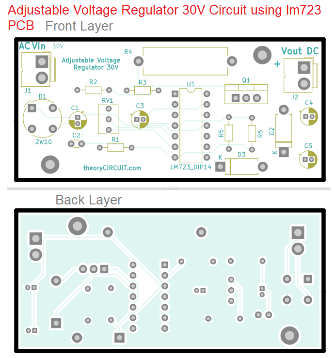
Interactive Board Viewer

