Last Updated on March 16, 2024
For an Hi-Fi amplifier tone control circuit is important this circuit controls bass and treble effects in audio output, different types of tone control circuit used in several applications here we listed top 5 tone control circuit which are easy to make and effective tone control circuits.
- Two transistor tone control circuit
- Tone control circuit using IC741
- Tone control circuit using LM1036
- Baxandall tone control circuit
- Active Baxandall tone control circuit
Two transistor tone control circuit
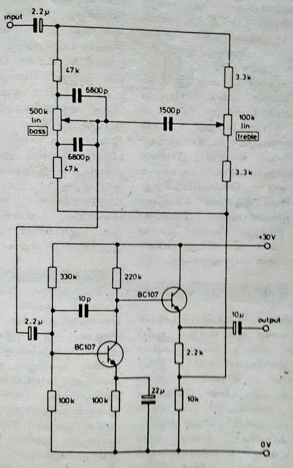
Two NPN transistors (BC107) are used in this circuit, this circuit is biased by 30 volt DC power supply, Audio input taken through the 2.2μfd capacitor and separated into two lines to control bass and treble effects, output from the tone control elements are fed into transistor pre amplifier, output is synchronized and then fed into the output pins here the output is taken from second transistor emitter terminal.
Tone control circuit using IC741
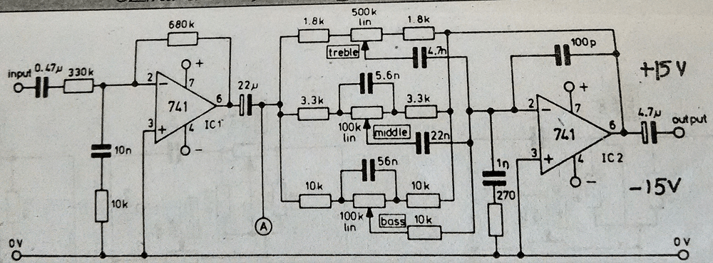
Two operational amplifier ICs are used in this circuit, first one is pre-amplifies the audio input and second stage operational amplifier gives tone controlled audio output with amplification, both operational amplifier uses inverting input pin as input. Output signal from the first amplifier is split into two by the baxandall circuit, this circuit provides bass, middle and treble tone controls over the audio signal, output from this circuit is amplified by the second stage amplifier.
Tone control circuit using LM1036
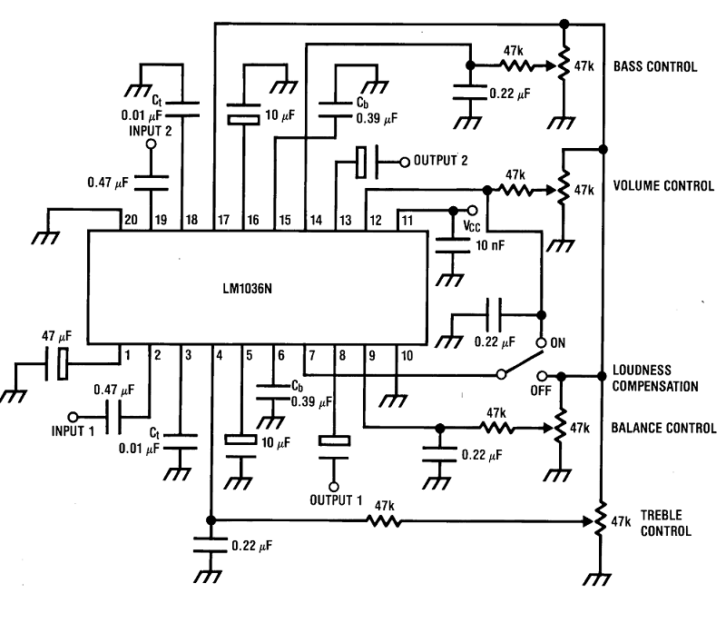
The IC LM1036 from texas instruments is a DC controlled tone control integrated circuit, this circuit provides dual bass, treble and balance volume output from audio signal, this IC is most suitable for stereo applications in car, radio and TV audio systems. This IC operates with 9 volt to 16 volt DC power supply and it has large volume control range 75 dB as typical, and it needs few external components to operate.
Tone Control IC LM1036 Pinout
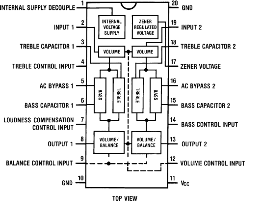
NOTE : (LM1036 is not recommended for new design)
Baxandall tone control circuit
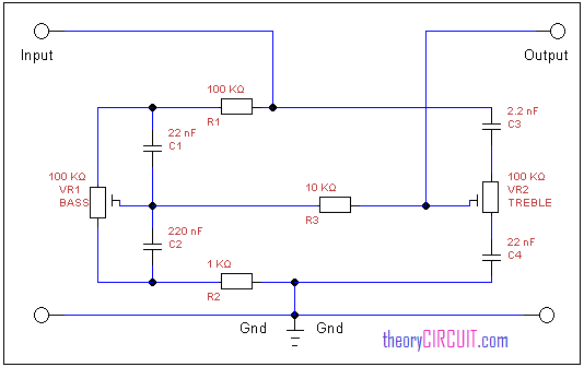
This is simple easy to construct few components passive tone control circuit, it has two variable resistors namely VR1 and VR2 these are controls bass and treble effect of audio signal, by using simple filtering process.
Active Baxandall tone control circuit
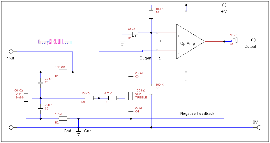
Here the baxandall tone control circuit is connected at the input of operational amplifier (IC 741) this amplifier connected with negative feed back.
Audio input is directly applied to the tone control circuit and then controlled audio signal is amplified by the operational amplifier and output is taken from the pin 6 of op-amp.
![]()
Datasheet of IC LM 741
Hi, in the Active Baxandall tone control circuit above, you have the negative feedback path connected to ground.
Yes, the “active” Baxandall circuit also uses the same values as would be appropriate for the lossy passive circuit, with the exception of the pots, which have been changed from log taper to linear. Carelessly lifted and not checked.
In the LM741 circuit what is point “A” ?
that’s i think for a balanced point if you have been made a stereo channel, maybe..
Here in this circuit the negative feedback is connected with output and can not connect with ground. Otherwise all in the circuit was correct.
you could’ve suggested a workaround or, as it seems, a placement of a resistor along the negative feedback line before the connection to ground – if indeed it needs it.
I need best tone control circult that can suit on mosfet amplifier
Hi, the last circuit of the active baxandall tone control can not work. The output of the op-amp is directly connected to the “Ground” (0V), please correct the circuit. This was also mentioned by C Hale, but nobody noticed it. It is a serious mistake, any beginner wanting to build this circuit is going to have a frustrating time trying to troubleshoot the circuit.
as mention by c hale and c Mltra,the output of the op amp is connected directly to ground…..any one who want to build this project,you should not connect the output to ground…ignore that part of the diagram
Pls I need a working 5-9v, low-mid-High tone control for my bass guitar asap,,,,,pls help me.
cut the feedback from ground