Last Updated on March 16, 2024
LED voltmeter circuit constructed by operation amplifier IC741, here the op-amps are acts as a level comparators and each op-amp output is connected with two LEDs to indicate the input voltage range.
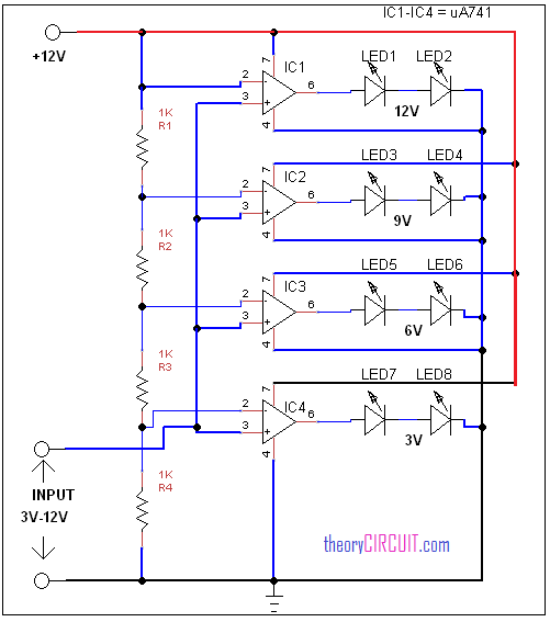
Circuit diagram for LED Voltmeter
Construction and Working
The inverting input from operational amplifier given to the voltage divider resistor network. Here each resistor R1 to R4 drops certain voltage from input and these drop voltage given to the comparator operational amplifiers, LED1 and LED2 indicates the voltage level upto 12 Volt, at the lowest range LED7 and LED8 indicates less than 3 Volt input.
Here each op-amp powered by 12 volt single power supply.
IC1 –> LEDs Indicates 12V
IC2 –> LEDs Indicates 9V
IC3 –> LEDs Indicates 6V
IC4 –> LEDs Indicates 3V