Last Updated on March 16, 2024
Simple Voltage Booster Circuit designed by using LM2698 from texas instruments. IC LM2698 is a simple switcher 1.35A Boost Regulator. Suitable for 3.3 V to 5 V and 5 V to 12 V conversion. The LM2698 device is a general purpose PWM boost converter.
IC LM2698 has 1.9-A, 18 V, 0.2Ω internal switch it enables the LM2698 to provide efficient power conversion to output ranging from 2.2 V to 17 V. It can operate with input voltages as low as 2.2 V and as high as 12 V.
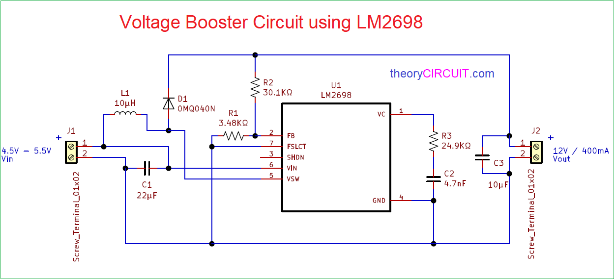
Circuit Diagram
Components Required
| 1 | C2 | 4.7nF | C_0805_2012Metric | 1 | ||
| 2 | C1 | 22µF | C_1210_3225Metric | 1 | ||
| 3 | C3 | 10µF | C_1210_3225Metric | 1 | ||
| 4 | R1 | 3.48KΩ | R_0805_2012Metric | 1 | ||
| 5 | R2 | 30.1KΩ | R_0805_2012Metric | 1 | ||
| 6 | R3 | 24.9KΩ | R_0805_2012Metric | 1 | ||
| 7 | L1 | 10µH | L_10.4×10.4_H4.8 | 1 | ||
| 8 | D1 | 0MQ040N | D_SMA | 1 | ||
| 9 | U1 | LM2698 | SOP65P490X110-8N | 1 | ||
| 10 | J1, J2 | Screw_Terminal_01x02 | TerminalBlock_Altech_AK300-2_P5.00mm | 2 |
Construction & Working
To Operate as a boost converter circuit IC2698 Requires few external components only. It have adjustable frequency operation from 600 KHz to 1.2 MHz by connecting pin 7 (FSLCT) to Vin we can get operation frequency to 1.25 MHz, ground to 600 KHz, in this circuit we have choosed 600 KHz operation and hence we connected pin 7 to ground.. If you need shutdown option then connect switch to pin 3 and Ground. It is a active low pin when it feds ground supply then shutdown occurs.
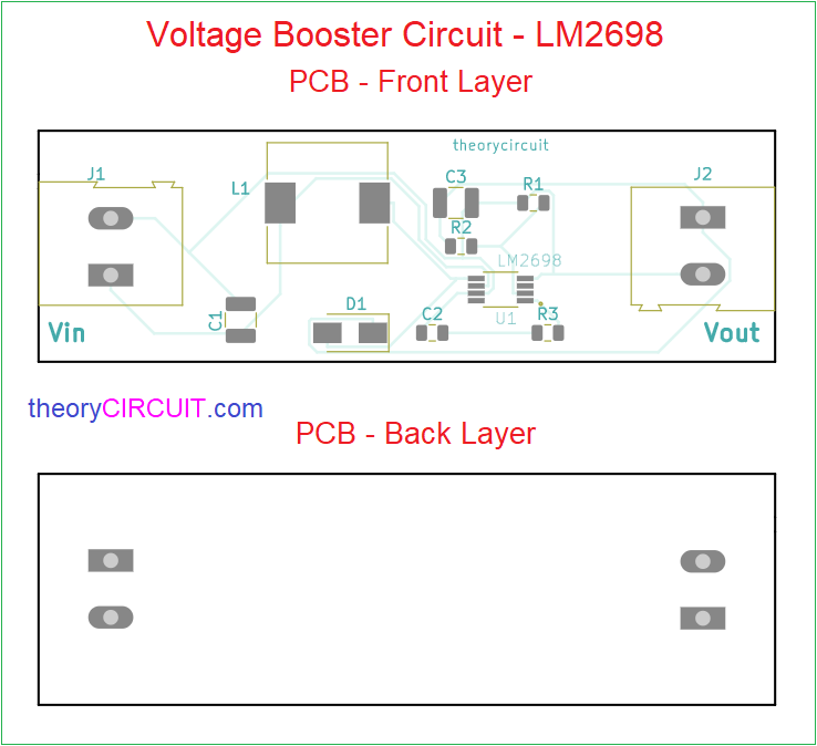
The LM2698 is available in a low profile 8 – pin VSSOP package. Hence we can design booster circuit in small size.
Printed Circuit Board (PCB)
Voltage Booster Circuit PCB Gerber files.
Interactive Board Viewer


How do I order this. I need to boost the 24 volts from a panel to several alrm horns.
Please advise.