Last Updated on March 16, 2024
NOTE: This circuit is not Recommended You can Consider the following Articles.
How to use 433MHz RF Transmitter and Receiver?
Wireless Switch using RF ASK Module
If you want to design a remote control using RF method then this circuit suitable for you, here we used 434MHz ASK (Amplitude Shift Keying) transmitter and receiver module to transmit and receive RF signal.
Circuit diagram
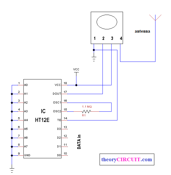
ASK Transmitter circuit

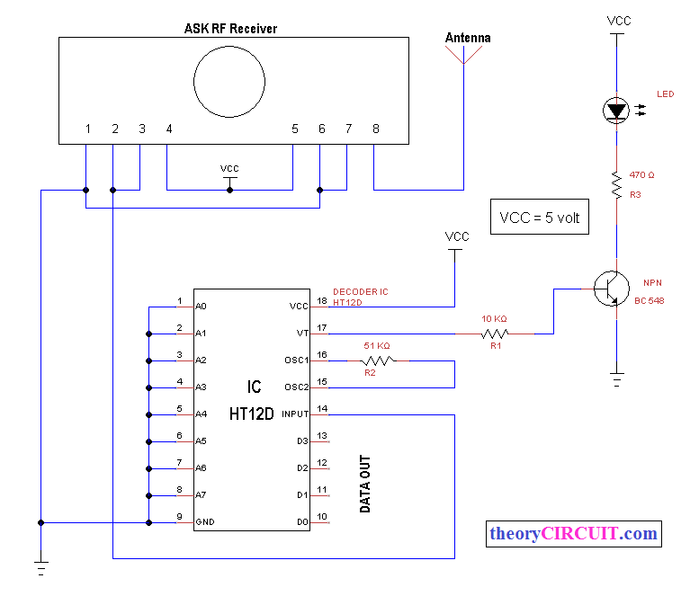
ASK Receiver circuit

The encoder (HT12E) and decoder (HT12D) used for unique purpose of sending key data and Receiving the key data.
The encoder can code the information of N address bits and 12 data bits, each one deals with two logic states, by the same decoder decodes the received signal from ASK receiver and give proper logic state at the output pins.
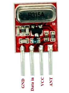
ASK Transmitter module
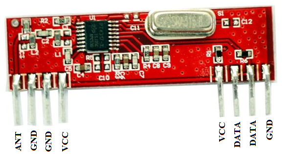
ASK Receiver module

Components List
| S.No | Name | Quantity |
| 1. | ASK 434MHz transmitter and Receiver module | 1 |
| 2. | IC HT12E IC HT12D |
1 1 |
| 3. | Resistor 1.1MΩ,5KΩ,10KΩ,470Ω | each 1 |
| 4. | LED | 1 |
| 5. | Transistor BC 548 npn | 1 |
Data sheet You can get IC HT12E data sheet here…
You can get IC HT12D data sheet here…

