
Last Updated on March 16, 2024
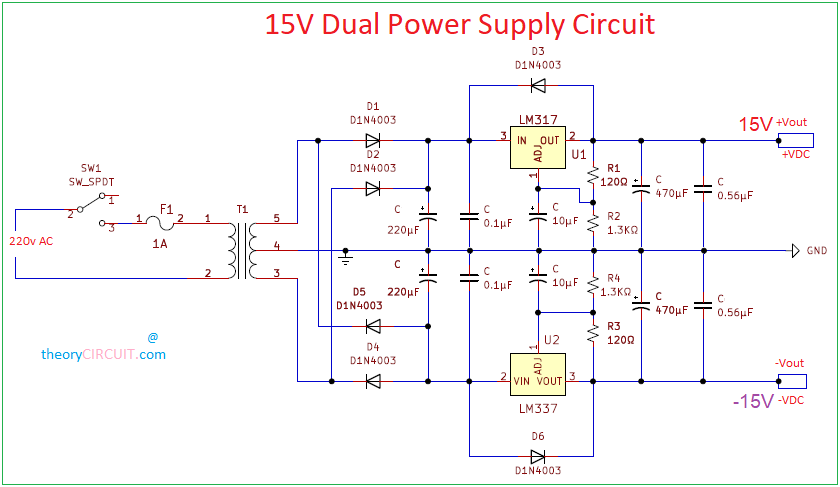
Robust 15V Dual Power Supply circuit designed by using IC LM317, IC LM337 and few easily available components. Construction of this 15V Power supply rail kept as simple as AC to DC rectifier and Regulator setup. In order to obtain 15 Volts at output 16-0-16V Centre tapped step down transformer used in this circuit. To form Bridge Rectifier Four D1N4003 Silicon rectifier diodes are used.
This 15V rail circuit takes direct AC Supply from 160V to 230V and gives +15V GND and -15V as DC output. Choose Step down transformer depends on your required output Current here 1A transformer used for prototype. Operational amplifier and Signal processing circuit can use this circuit as bias source.
Circuit Diagram
BOM
| S No | Designator | Value | Quantity |
| 1 | Center Tapped Transformer | 16-0-16V | 1 |
| 2 | SPDT | 1 | |
| 3 | Fuse | 1A | 1 |
| 4 | D1,D2,D3,D4,D5,D6 | D1N4003 | 6 |
| 5 | R1,R3 | 120 | 2 |
| 6 | R2,R4 | 1.3K | 2 |
| 7 | Capacitor electrolytic | 220uF | 2 |
| 8 | Capacitor disc | 0.1uF | 2 |
| 9 | Capacitor electrolytic | 10uF | 2 |
| 10 | Capacitor electrolytic | 470uF | 2 |
| 11 | Capacitor disc | 0.56uF | 2 |
| 12 | IC(positive voltage regulator) | LM 317 | 1 |
| 13 | IC(negative voltage regulator) | LM 337 | 1 |
Construction and Working
This general purpose dual power supply circuit is designed to deliver 1A 15V rail supply however you can obtain different voltage level and current at output through modifying Voltage regulators and stepdown transformer. To give detailed view of this circuit lets start the design with the following pattern.
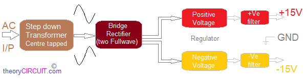
As you see this dual power supply circuit designed with four stages, First one is Stepdown transformer, as we know to reduce input AC supply Amplitude we use this device. Here 16-0-16 V AC secondary transformer used. Before employ the Transformer in to the circuit check the primary and secondary sides. Second stage is Rectifier stage, here four Silicon diodes are used to form bridge rectifier and DC output from this rectifier taken as Positive and Negative with respect to Neutral line (GND) of step down transformer.
Positive Voltage Regulator
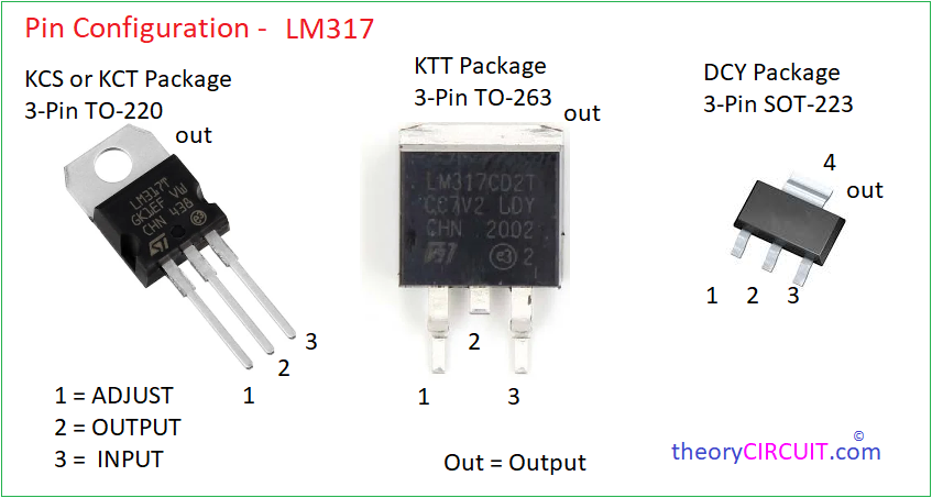
IC LM317 is a three terminal Adjustable Positive Voltage Regulator from Texas Instruments. This IC comes in different packages and capable of delivering 1.5A over a output voltage range from 1.25V to 37V here we have configured output of this IC as 15V DC. Refer Datasheet for Vout Calculations.
Negative Voltage Regulator

IC LM337 and LM137 is a three terminal Adjustable Negative Voltage Regulator from Texas Instruments. This IC comes in different packages and capable of delivering -1.5A over a output voltage range from -1.25V to -37V here we have configured output of this IC as -15V DC. This IC also requires two external IC to fix the output voltage level as same as the Positive voltage regulator. Refer Datasheet for Vout Calculations.
Separate 470μF Electrolytic Capacitor and 0.56μF disc capacitor used as a filter element for both Positive and Negative Voltage DC output line. +Ve 15 Volts and -Ve 15 Volts can be tested with Respect to GND (Ground line) obtained from centre tap of Stepdown transformer.
Your capacitors are too small for 1A load. The 16vac has a peak of 22.6Vdc. The diode drop in this full wave centre tap configuration will be 1v at full load, at least so available peak is 21.6 Vdc. The regulators will need 3v head room = 15 +3 =18. So the maximum ripple is 21.6-18 = 3.6 V
The capacitance required to filter the 10ms period full wave (Australia uses full wave rectification, so 100Hz) is given by
C = I * delta T / delta V
C = 1A* 10ms / 3.6V = 2.8mF = 2800 uF