
Last Updated on March 16, 2024
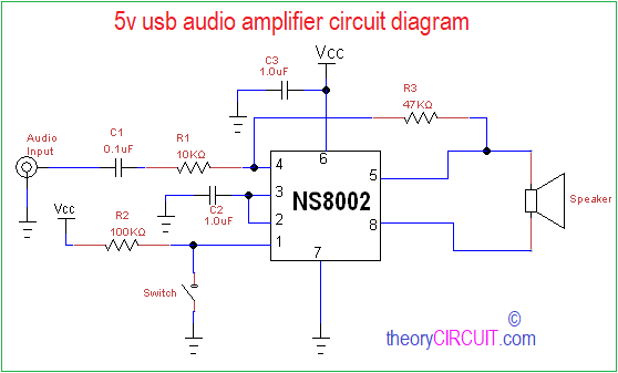
Small power portable Audio amplifier design requires minimum components utilization and low power consumption, here the 5V USB audio amplifier circuit diagram composed with NS8002 will give continuous 3 watts output and this amplifier circuit don’t have any output coupling capacitor or bootstrap capacitors hence the size of amplifier shrink into compact size for hand held applications.
The NS8002 has some important features such as low power consumption shutdown mode (very helpful for battery powered devices), It eliminates turn on/off transition noise, It has unity gain and can be configured by external gain setting resistor.
Circuit Diagram
Construction & Working
This Amplifier IC NS8002 takes wide range of voltages between 4.0V to 6.0V and it is most suitable for USB powered applications. Due its internal elements this circuit requires few external resistor and capacitors only. IC NS8002 pin 1 is called as SD pin, this amplifier enters into shutdown mode when a high level is applied on SD pin, there is a switch connected between pin 1 and ground it represents low level if the switch gets open then high level is applied. Pin 2 is called as BYP, Bypass capacitor pin which provides the common mode voltage. Pin 3 is +IN positive input of the first amplifier and receives the common mode voltage through C2 capacitor.
Pin 4 is -IN Negative input of the first amplifier, receives the audio input signal through coupling capacitor C1 and R1 Resistor. Pin 5 is Vo1 it gives negative output for loud speaker. Pin 6 is Vcc and takes Analog Vcc input supply (+5V), pin 7 is GND and takes ground connection for circuitry. Pin 8 is Vo2 it gives positive output for loud speaker. Resistor R3 employed as feedback resistor between input and output.
8002 Amplifier Module
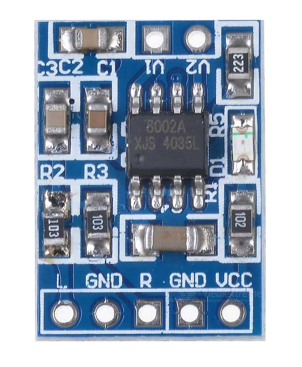
NS8002 available in different easy to interface breakout board, and can be instantly employed in applications without lot of soldering works.
USB power lines
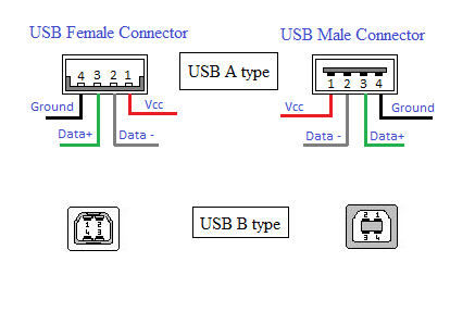
Take Vcc and Ground wires only to provide power supply (5V) to this amplifier circuit and avoid Data+ and Data- terminals.
Note:
- Apply DC supply voltage (5V)
- Use 4 ohm loud speaker for best response.
your ckt is a good but when i will make then i will tell more
sony TA DX8 BROAD AMPLIFIER HOW TO GET AUDIO USB OR LINE IN
Thanks alot for influence, may God bless you.
How to connect audio input to the circuit??
L and R,to C1.It will be OK !
Thanks dear admin for circuit diagram