Last Updated on March 16, 2024
Passive Filter Circuit can be made by Resistor, Capacitor and Inductor. We know signal filters are made to allow or stop particular frequency signal. By using passive elements Resistor and Capacitor we can make the following filters.
- Low Pass Filter
- High Pass Filter
- Band Pass Filter
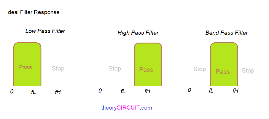
Input signal to the circuit may have different level of frequency, here we can fix lower cutoff frequency (fL) or Higher cutoff frequency (fH) and allow or stop particular frequency signal to the circuit.
Ideal Filter Response
Ideal filter response for low pass, high pass and band pass filters clearly show the frequency and amplitude level of output signals from filters.
Low Pass Filter (RC)
Simple Resistor and capacitor across the input signal can form the passive low pass filter circuit.
It allows the input signal frequency below the lower cutoff frequency level. By changing the value of Resistor and capacitor we can change the cutoff frequency level.

Here Fc represents cutoff frequency and RC is the value of Resistor and capacitor.
High Pass Filter (RC)
By using simple Resistor and Capacitor we can design high pass filter circuit.
High pass filter formed by connecting capacitor series to the input signal and connecting Resistor parallel to the input signal.

Here Fc represents cutoff frequency and all the input signal above the cutoff frequency allowed through this filter.
Band Pass Filter (RC)
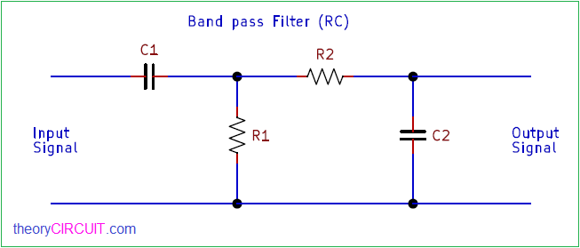
This passive band pass filter designed to allow particular frequency signal and to stop remaining signal.
By connecting high pass filter and low pass filter we can form band pass filter, here we need to carefully calculate lower cutoff frequency and higher cutoff frequency.

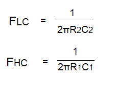
Here FLC represents lower cutoff frequency calculations and FHC represents higher cutoff frequency calculations. Above three passive filters are designed by using Resistor and capacitor elements, we can also design the same by using Resistor and Inductor elements.


