Last Updated on March 16, 2024
Blown Fuse Indicator will help us to identify fault quickly, We use different types of Circuits and application board, here the most burning device will be the fuse element. We can’t completely avoid this fuse element because it protects the circuit elements from high current draw and voltage surges.
In this article two types of prototype circuit given and these circuits will indicate the blown fuse. Following Blown fuse indicator circuits are designed for DC circuit.
Circuit Diagram
Simple Blown Fuse Indicator
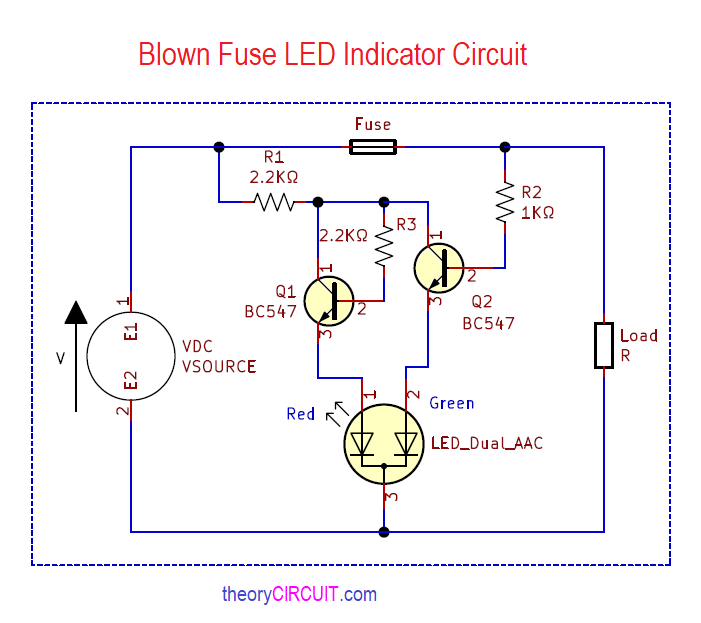
Dual LED Blown Fuse Indicator Circuit
Components Required
For Simple Blown Fuse Indicator
- Resistor 1KΩ = 1
- LED 5mm = 1
For Dual LED Blown Fuse Indicator Circuit
- Resistor 2.2KΩ = 2
- Resistor 1KΩ = 1
- Transistor NPN BC 547 = 2
- bi-color LED Red,Green CC – 1
Construction & Working
Simple Blown Fuse Indicator Circuit has only Resistor and LED connected in series and then paralleled with target fuse. When we apply DC supply to Load through this fuse and circuit setup, due to the low Resistance in the Fuse wire current will easily flow through it and there is no current flow through Resistor and LED hence the LED stays in OFF condition.
If the fuse blown for some reason then there is no current flow through open fuse, then here the current flow occurs through Resistor and LED only, so the LED starts to glow (that is ON) by the way it indicates the blown fuse.
Dual LED Blown Fuse Indicator Circuit Uses Bi-Color LED (Red,Green) to indicate the fuse status like Green indicates good fuse and Red LED indicates the blown fuse. Here the transistors Q1 and Q2 acts as switch, Both transistor gets collector bias through R1 Resistor, Q2 transistor base gets bias through R2 Resistor and it gets supply after the fuse element. Green LED terminal is connected with the Q2 transistor emitter. Good fuse conducts supply and then Q2 gets base bias so the Green LED glows.
R3 Resistor gives high Resistance to the base bias of Q1, if the fuse is good then Q2 transistor stays in ON condition. If the fuse blown for some reason then Q2 transistor don’t get base bias through R2 hence Q2 becomes turn OFF. Here Q1 transistor gets minimum base bias through R3 Resistor hence Q1 starts conducting (ON) from saturation condition, so the Red LED connected to the Q1 emitter starts to glow and indicates the fault in fuse.


For Simple Blown Fuse Indicator:
If the LED blocks, the maximum reverse voltage may be exceeded. It is better to switch a second diode anti-parallel to te LED.