Last Updated on October 1, 2025
3W Class D Audio Amplifier designed by using IC PAM8403, This IC is a filter less 3W Class D stereo Audio Amplifier, with few easily available external components Simple PAM8403 Amplifier Circuit designed.
IC PAM8403 Offers low THD+N allowing it to achieve high quality sound reproduction. This IC can directly drive Output Speakers. It can give 3W output with 4Ω Loud Speaker and 5V Power Supply and also provides efficiency up to 90%.
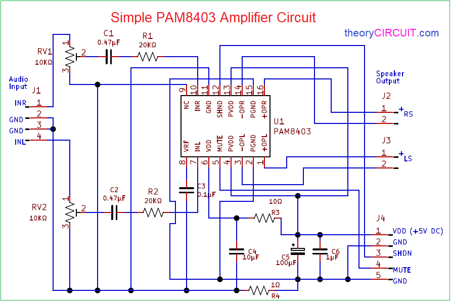
Simple PAM8403 Amplifier Circuit Diagram
Components Required (BOM)
| 1 | C1, C2 | 0.47µF | C_0805_2012Metric | 2 | ||
| 2 | C3 | 0.1µF | C_0805_2012Metric | 1 | ||
| 3 | C4 | 10µF | C_0805_2012Metric | 1 | ||
| 4 | C5 | 100µF | C_0805_2012Metric | 1 | ||
| 5 | C6 | 1µF | C_0805_2012Metric | 1 | ||
| 6 | R1, R2 | 20KΩ | R_0805_2012Metric | 2 | ||
| 7 | R3 | 10Ω | R_0805_2012Metric | 1 | ||
| 8 | R4 | 1Ω | R_0805_2012Metric | 1 | ||
| 9 | U1 | PAM8403 | SO-16_3.9×9.9mm_P1.27mm | 1 | ||
| 10 | RV1, RV2 | 10KΩ | Potentiometer_Bourns_3266W_Vertical | 2 | ||
| 11 | J2, J3, J5 | Conn_01x02_Male | PinHeader_1x02_P2.00mm_Vertical | 3 | ||
| 12 | J1 | Conn_01x04_Male | PinHeader_1x04_P2.00mm_Vertical | 1 | ||
| 13 | J4 | Conn_01x05_Male | PinHeader_1x05_P2.00mm_Vertical | 1 |
Construction & Working
IC PAM8403 comes in SOP-16 Package hence it occupies minimum PCB space, Analog VDD and Power VDD supply applied from J4 Connector. Power GND and Analog GND also applied from J4 Connector, Mute and SHND (Shutdown) Pins are Active low pins when applying GND supply to these pins we can mute and shutdown the PAM8403 from its operation.
Connector J1 acts as a Audio Input terminal, here stereo input Right and left channel audio signals from source connected, then to the IC through variable Resistor and Capacitor filter. Output Audio signal for Right loud speaker connected in J2 and output signal for Left loud speaker connected in J3 connector. By varying the RV1, RV2 variable Resistors we can control the output volume in loud speaker.
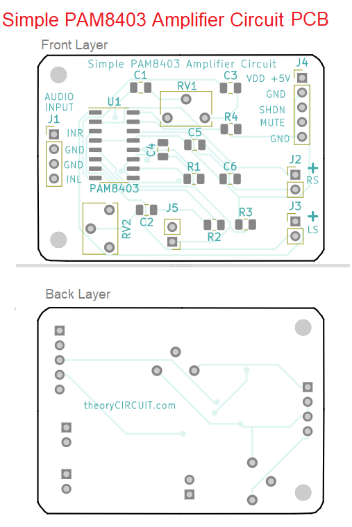
Printed Circuit Board
Simple PAM8403 Amplifier Circuit PCB Gerber Files.
Interactive Board Viewer
PAM8403 Audio Amplifier Board
Ready made PAM8403 Audio Amplifier Board in action.


What is the purpose of the R4 resistor of value 1 ohm?
It is to Reduce noise at Audio input Signal and to separate Power supply GND.