Last Updated on March 16, 2024
We know Audio Amplifiers like Class A and Class AB operate by continuously varying the current through the output transistor to replicate the input signal. Unlike those amplifiers, Class D amplifiers take a different approach. They utilize pulse-width modulation (PWM) to encode the audio signal into a series of on/off pulses. This digital methodology significantly enhances efficiency and reduces power dissipation. Here Simple Class D Amplifier Circuit designed by using TPA3122D2 analog input Class-D audio amplifier integrated circuit from Texas Instruments.
How Class D Audio Amplifier Works?
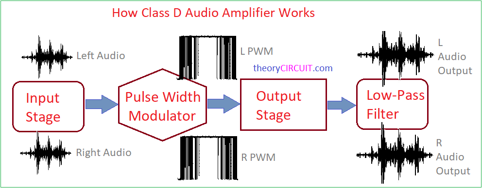
A Class D Audio Amplifier Schematic will have the four basic blocks,
- Input Stage.
- Pulse Width Modulator
- Output Stage
- Low-Pass Filter
Here the input stage of a Class D amplifier consists of a comparator that compares the audio input signal with a high-frequency triangular waveform. This process generates a series of pulses, marking the foundation of the digital signal. Then the pulse width modulator is the core element responsible for converting the analog input signal into a digital pulse train. The width of these pulses represents the amplitude of the input signal. The amplified digital signal is then fed into the output stage, comprising a pair of power MOSFETs (Metal-Oxide-Semiconductor Field-Effect Transistors). These transistors rapidly switch on and off, producing a high-frequency square wave. To retrieve the original audio signal, a low pass filter is employed at the output stage. This filter eliminates the high-frequency components, leaving behind a smooth amplified audio signal.
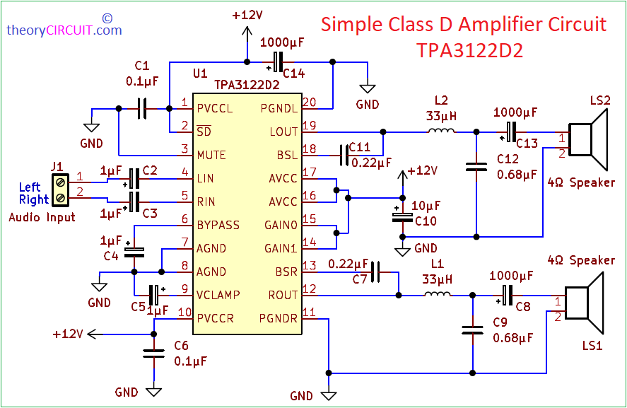
Circuit Diagram
Components Required (BOM)
| 1 | C2, C3, C4, C5 | 1μF | CP_Radial_D8.0mm_P3.80mm | 4 | ||
| 2 | C8, C13, C14 | 1000μF | CP_Radial_D13.0mm_P5.00mm | 3 | ||
| 3 | C1, C6 | 0.1μF | C_Disc_D3.0mm_W2.0mm_P2.50mm | 2 | ||
| 4 | C7, C11 | 0.22μF | C_Disc_D3.0mm_W2.0mm_P2.50mm | 2 | ||
| 5 | C9, C12 | 0.68μF | C_Disc_D3.0mm_W2.0mm_P2.50mm | 2 | ||
| 6 | C10 | 10μF | CP_Radial_D8.0mm_P3.80mm | 1 | ||
| 7 | L1, L2 | 33μH | L_Axial_L30.0mm_D8.0mm_P35.56mm_Horizontal_Fastron_77A | 2 | ||
| 8 | U1 | TPA3122D2 | DIP-20_W7.62mm | 1 | ||
| 9 | LS1 | 4Ω Speaker R | TerminalBlock_Altech_AK300-2_P5.00mm | 1 | ||
| 10 | LS2 | 4Ω Speaker L | TerminalBlock_Altech_AK300-2_P5.00mm | 1 | ||
| 11 | J1 | Audio Input | TerminalBlock_Altech_AK300-2_P5.00mm | 1 | ||
| 12 | J2 | power supply | TerminalBlock_Altech_AK300-2_P5.00mm | 1 |
Construction & Working
The TPA3122D2 is a simple Class D audio amplifier integrated circuit manufactured by Texas Instruments, renowned for its exceptional performance in audio applications. It can drive Stereo speakers or mono bridge tied speaker. It can operate with 10V to 30V power supply and gives up to 15 Watt Audio output power. Due to having efficient Internal Oscillator this IC don’t requires External oscillator. The gain of the amplifier is controlled by two gain select pins (GAIN0, GAIN1). The gain selections are 20, 26, 32, and 36 dB. It comes in 20 pin DIP package, due to internal Thermal and Short-Circuit Protection, no need for heatsink.
Construction of this simple Class D audio amplifier circuit is very simple, because we are going to use only single IC. TPA3122D2 contains all the stages and circuitry required for Class D amplifier. We Just need few External capacitors and loud speakers. The TPA3122D2 employs a pulse-width modulation (PWM) technique to convert analog audio signals into a series of digital pulses. In the input stage, the audio signal is compared with a high-frequency triangular waveform by a comparator.
This process generates a digital representation of the audio signal, with the width of the pulses corresponding to the amplitude of the input. The TPA3122D2 then utilizes an internal feedback network to regulate the output and ensure stability. The output stage involves power MOSFETs that rapidly switch on and off in response to the digital pulses, producing a high-frequency square wave. Subsequently, an output filter, consisting of an output inductor and filter capacitors, smoothens the signal and removes high-frequency components, resulting in a clean and amplified audio output. Two 4Ω Loud speakers connected at the output end to reproduce audio signal.
There are two main configurations that may be used. For stereo operation, the TPA3122D2 should be configured in a single-ended (SE) half bridge amplifier. For mono applications, TPA3122D2 may be used as a bridge tied load (BTL) amplifier. This TPA3122D2 use traditional class-D modulation scheme, which is used in the TPA3122D2 BTL configuration, has a differential output where each output is 180 degrees out of phase and changes from ground to the supply voltage, VCC. Therefore, the differential pre-filtered output varies between positive and negative VCC, where filtered 50% duty cycle yields 0 V across the load. Refer Datasheet for more details.
Printed Circuit Board
Simple Class D Amplifier Circuit PCB Gerber File.
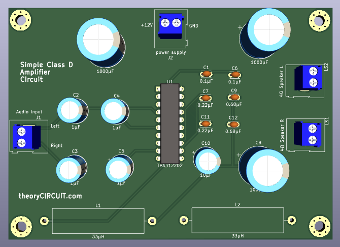
Simple Class D Amplifier Schematic using TPA3122D2 – PCB Front Layer.
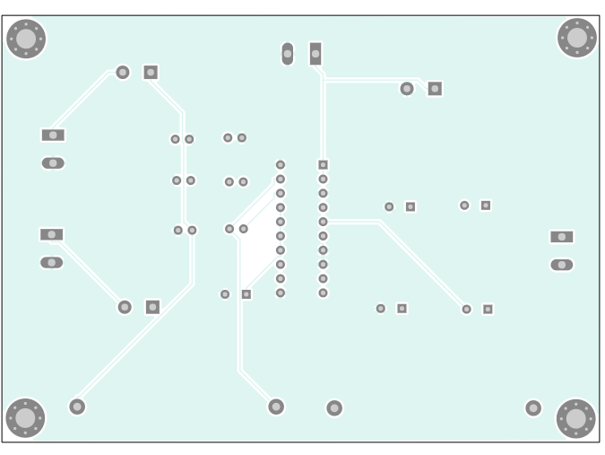
PCB Back Layer.
Interactive Board Viewer


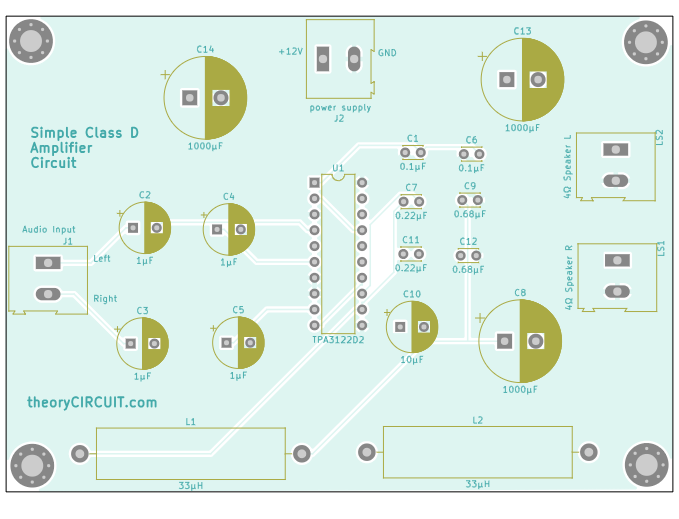
Class D Audio Amplifier PCB 3D View