Last Updated on January 19, 2025
Three passive components Resistor (R), Inductor (L) and Capacitor (C) connected in series or parallel to the power source forms RLC circuit. This is used in Signal Filter like low pass, high pass, band pass, or band stop filters, particularly isolating certain frequency ranges. and then used in Tuned Circuits like in radios, TV tuners, and oscillators to select desired frequencies. Here the following RLC circuit resonant frequency and quality factor calculator will help you to get exact values.
RLC Circuit Calculator
Select the RLC circuit type either series or parallel to get exact output values.
RLC Series Circuit
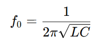
To Calculate Resonant frequency (fo) for the RLC Series Circuit, we used the following formula

RLC Series Circuit Quality Factor (Q)

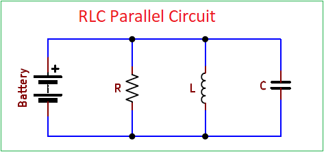
RLC Parallel Circuit
To Calculate Resonant frequency (fo) for the RLC Parallel Circuit, we used the following formula (for both series and parallel RLC circuit same formula used)

RLC Parallel Circuit Quality Factor (Q)


