Last Updated on August 9, 2026
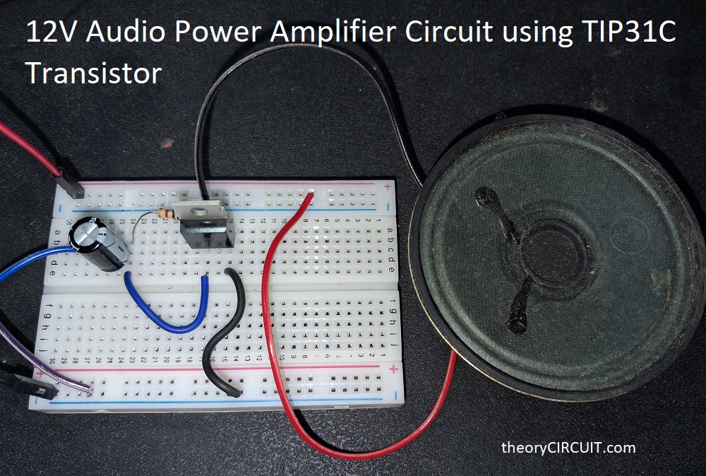
Here we are going to build a very simple and beginner friendly 12V Audio Power Amplifier Circuit using TIP31C Transistor and configure as a class A amplifier. It requires only three components to build. This is one of the easiest ways to understand how a transistor can be used not just as a switch, but as a linear current boosting device for audio signals. This circuit helps any one who wants to build or understand power amplification from first principles before jumping into IC based amplifier module like the LM386 or TDA2030 etc.
For an commercial audio amplifier, Audio chain like buffer amplifier, pre-amplifier and power amplifier are important to pass the audio signal, boost a weak signal and then deliver power to a low impedance load speaker. But here we build a quick power audio amplifier to deliver the voltage and current through TIP31C NPN transistor based on the input audio signal., So the speaker gets enough power (Voltage x Current) to move and produce sound from cone. Remember some fluctuating noise may rise during the absence of audio signal due to the current flow through speaker coil and transistor.
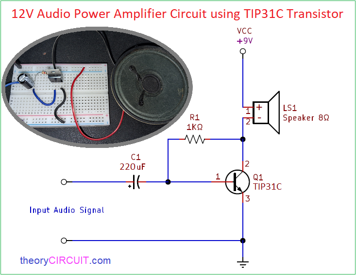
Circuit Diagram
Components Required
- Transistor TIP31C (NPN)
- Electrolytic Capacitor 220μF/25V
- Resistor 1KΩ
- Speaker (4Ω or 8Ω)
Working Video
Features
- This circuit employs simple 3 component.
- Runs from 3.3V to 12V DC supply (make sure your speaker handles that voltage)
- Class A biasing for low distortion at low power levels.
- Can be built on a breadboard in a few minutes.
- Can be extended later into push-pull or class AB design for better efficiency.
Construction & Working
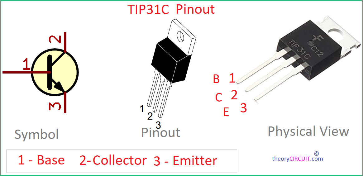
TIP31C Transistor Pinout
Just make the wiring as shown in the circuit diagram. Speaker positive terminal goes to +Vcc (3.3V to 12V) and negative terminal goes to collector pin of TIP31C. Audio signal from the input jack passes through 220μF coupling capacitor to base terminal of TIP31C transistor. This C1 blocks any DC from the audio source and lets only AC audio signal to the base. 1KΩ resistor between collector terminal to base terminal of TIP31C provides the DC bias current needed to keep the transistor in partially ON state that is class A state for audio. Emitter terminal goes directly to ground.
Here we use power transistor TIP31C and it may require heatsink, attach one if you are going to use this circuit long on 12V supply. Use 4Ω to 8Ω load speaker. Since the speaker itself acts as the collector load, small variations in base current that is driven by the incoming audio signal cause proportionally large variations in collector current through the speaker coil, so that changing current is what physically moves the speaker cone and reproduces sound.
Amplifier circuit on breadboard