Last Updated on March 16, 2024
FM Transmitter, I think every electronics maker may tried out. In this Project an FM Transmitter made out with KT0803K based board and it is controlled by famous Arduino UNO board. It transmits our voice through Frequency Modulation between 70MHz to 108MHz.
IC KT0803K Block diagram
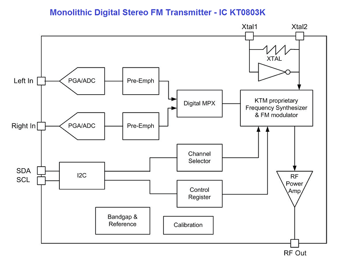
Monolithic Digital Stereo FM transmitter IC KT0803K from KTMicro capable of producing 70 MHz – 108 MHz standard FM with Ultra low power consumption 17mA operation current from single power supply. By using I2C wires (SDA, SCL) Micro controller Unit can decide the channel frequency and control the KT0803K as a slave.
This IC contains on chip 20-bit Audio ADC to convert Left in, Right in audio into digital signal. On chip DSP core is well enough to handle the digital audio signals. FM modulator output is Amplified by RF power amplifier and bring out to antenna through RF out pin. This IC comes in 16-pin SOP package, operating voltage varies between 1.6 V to 3.6 V and compatible IC for programmable FM transmission.
FM Transmitter Module
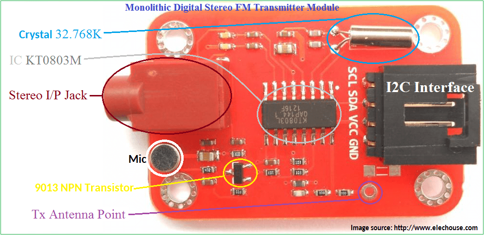 FM transmitter module from elechouse, this board contains monolithic digital stereo FM transmitter IC KT0803K which is responsible to make FM over our Audio input and this IC directly controllable by Arduino board (Microntrollers) through I2C interface.
Stereo input jack given for audio input from external device and also this module has on-board mic to pickup our voice. Audio signal from the mic amplified through 9013 npn transistor and applied to the tx IC. 32.768 K Crystal provides clock to this module.
By two wire standard I2C-Microcontrollers can control this FM module and KT0803K requires no external tuning.
Arduino Hookup-FM transmitter
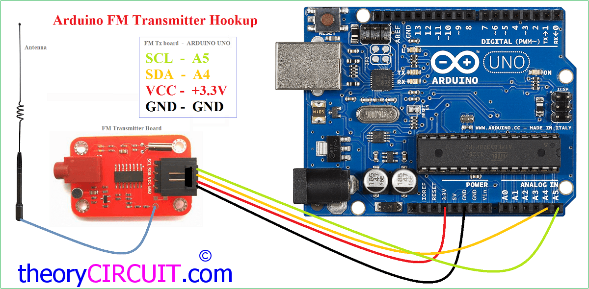
Connect the FM transmitter module with Arduino board as shown in hookup diagram. Here Vcc pin of module connected to Arduino’s 3.3V power supply pin, and Ground is connected to GND of Arduino board. I2C Pins SDA and SCL connected to A4 and A5 of arduino uno board because these two are I2C pins in uno board. It change depends on types of arduino board and micro controllers, check the pin details if other board is used.
Arduino FM transmitter schematic
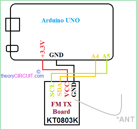
It just given for details and connections are made as shown in the hookup. Any single wire can act as Antenna.
Warning Note:-
[stextbox id=”warning”]In most countries-it is illegal to build personal radio station which covers large area. Some FM bands are requires license too. Check for the free to use FM band according to your country and make sure it would not affect with neighbors.[/stextbox]
Arduino Code – FM transmitter
/**
 Project done by www.theorycircuit.com

    For this demo, input command format like &xxxx to set select band,
 (eg:if you want to set FM 95.6MHz,then input &0956 and send).

Credits to: www.elechouse.com.
*/

#include <FMTX.h>

float fm_freq = 90;  // Here set the default FM frequency
void setup(void)
{

  Serial.begin(9600);
  Serial.print("FM-TX Demo\r\n");
  /**
  Initial, set FM channel and select your area:
 USA
 EUROPE
 JAPAN
 AUSTRALIA
 CHINA
  */
  fmtx_init(fm_freq, USA);
  Serial.print("Channel:");
  Serial.print(fm_freq, 1);
  Serial.println("MHz");
}

void loop(void)
{
  /** check for data setting new frequency.  Users could input data from Serial monitor. Data
    must start with '&' and followed by 4 numbers, such as &8000. The first two is the integer part
    of new frequency (Unit: MHz), and the last one is the decimal part. And the channel must between 70MHz
    and 108Mhz. For example,  &756 is 75.6MHz, and &666 is out of range.
  */
   if(Serial.available()){
    switch(Serial.read()){
      case '&':
        u8 i,buf[4];
         float ch;
         i=0;
         delay(30);
         while(Serial.available()&&i<4){
           buf[i]=Serial.read();
           if (buf[i]<= '9' && buf[i]>= '0') {
           i++;}
           else{
           i=0;
           break;
           }
         }
         if (i==4){
           ch = (buf[0]-'0')*100+(buf[1]-'0')*10+(buf[2]-'0')*1+0.1*(buf[3]-'0');
           if(ch>=70&&ch<=108){
             Serial.print("New Channel:");
             Serial.print(ch, 1);
             Serial.println("MHz");
             fmtx_set_freq(ch);
           }else{
             Serial.println("ERROR:Channel must be range from 70Mhz to 108Mhz.");
           }
         }else{
           Serial.println("ERROR:Input Format Error.");
         }

         while(Serial.available()){
           Serial.read();
         }
        break;
    }
  }
}
This code requires Library file, you can get it here.
how long is the range this Transmitter can cover?
About few kilo meters.
May be 600 to 700 meters .
Cant get this to work, no errors but i cant seem to tune into what im playing
Don’t forget that the frquency range begins at 70MHz!
If your tuner is a “normal” radio it only starts to tune at 87… so be sure that you have selected a frequency in the range that your tuner tuneS!
(sorry if it is not that – I have no ideia if you’re a newb or an expert)
Hi, can this module support RDS?
No, it cannot. The RDS has to be injected at the varacap in the VFO circuit. The chip has no connection to do so.
what about the power supply
Hi everybody,
How can I transmit a audio signal using ESP-8266 over a webserver? (I am in process of making a web radio where I need to transmit my own voice using ES-8366 & offcourse mic)
I mean can I use general IP/OP pins for that or I need to use something else?
Kindly let me know if anyone has done this.
Thanks in advance 🙂
Looking forward
it said , not found Library
Como add um lcd oled nesse circuito