Last Updated on April 8, 2024
Boost Converter Circuit Using MC34063 IC is designed with few external components and this IC is suitable for compact DC/DC boost converter circuit. The IC MC34063 is contains all the primary circuitry needed for building simple DC-DC converters.
Following Circuit is designed to boost Input voltage from 5V to 10V using single power supply source. This boost converter circuit is most suitable to drive or bias output actuators in the microcontroller or microprocessor based design.
A short Notes on DC-DC Boost Converter
A DC-DC boost converter is an electronic circuit that takes a lower DC voltage as input and increases it to a higher DC voltage at the output. It essentially “boosts” the voltage level, making it a crucial component in various electronic applications. The primary purpose of a boost converter is to address situations where the available voltage is insufficient for the requirements of a particular device or circuit. If you are using battery as a power source and it is limited to some voltage levels like 6V, 9V etc.., if your circuit elements need 12V or more then you don’t have to go for other power source, you can simply use this kind of DC-DC boost converter circuit to increase present power source to desired level and you can use both power supply.
IC MC34063
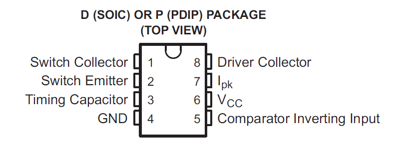
IC MC34063 Has wide input supply range between 3V to 40 Volt, It can provide high output switch current up to 1.5A we need to provide specific inductor. It can provide adjustable output voltage and has short circuit current limiting and low standby current. By using few external components we can implement this IC into buck, boost and inverting topologies.
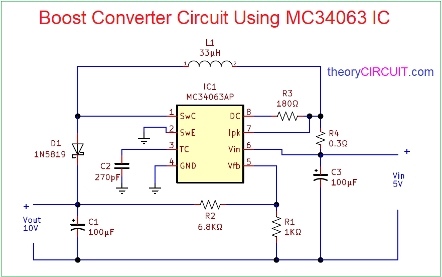
Circuit Diagram
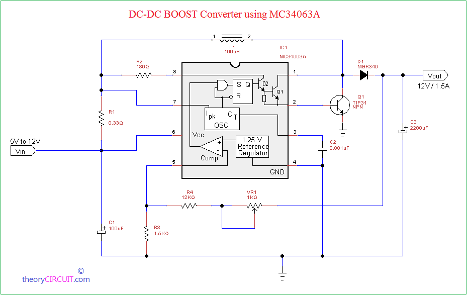
Another Boost Converter circuit using MC34063
Components Required
- IC MC34063AP
- Schottky diode 1N5819
- Inductor 33µH
- Capacitor 100µF = 2
- Capacitor 270pF
- Resistor 0.3Ω, 1KΩ, 6.8KΩ, 180Ω each one
Construction & Working
Here IC MC34063 is implemented as DC-DC Boost converter and it will give output as 10V using input supply 5V, Connect every components as near as possible to the IC. After connecting all components in the circuit calculate the output voltage by using the following formula.
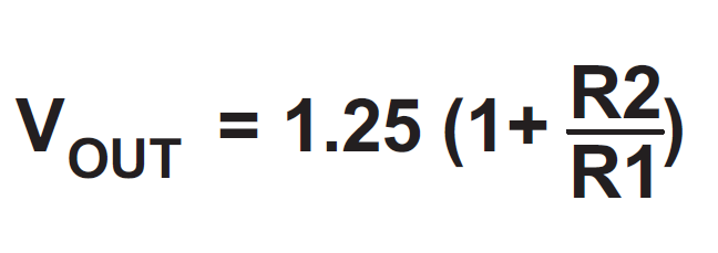
And take it as a theoretical output voltage range and apply bias to the circuit and check the output voltage and compare both. Due to the inductor value and specification the practical output voltage may vary slightly.
By using the internal temperature compensated reference, a comparator, an oscillator (100KHz), a PWM controller with active current limiting, a driver and a high current output switch this IC MC34063 can provide Specific output required for your design. Refer datasheet for more calculations.
This DC-DC buck/ boost switching regulator can be used in Telecommunication devices, portable electronic devices, Test & Measurement devices and consumer electronic devices.
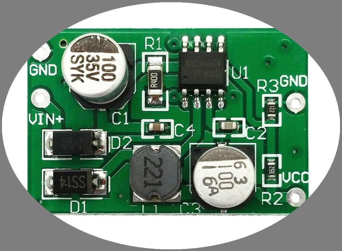
MC34063 Boost Converter Circuit SMD Version Available in Market
Further
Datasheet of MC34063 from onsemi.
to increase current up to 1.5A for the same IC then which component i need to add?
Refer datasheet there you will find External Component Value Calculation depends on that you can choose external components to achieve 1.5A Current output.
Booting circuit mc34063 step up wiring schematic diagram
Lityum piller içinde uygun bir entegre varmı? 3.3 Volta sabit tutacak
How can I calculate the external component’s values, particularly for dimensioning the internal oscillator ?
Hi Aruna,
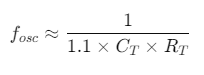
To calculate the oscillator frequency for the MC34063, use Fosc Formula from datasheet, where Ct is timing capacitor and Rt is an internal resistor (1.1 kΩ to 1.4 kΩ). For a desired frequency, rearrange to find Ct, Inductor L is calculated based on the configuration (buck, boost, or inverter) using the input/output voltages, desired ripple current, and frequency.