Last Updated on December 14, 2024
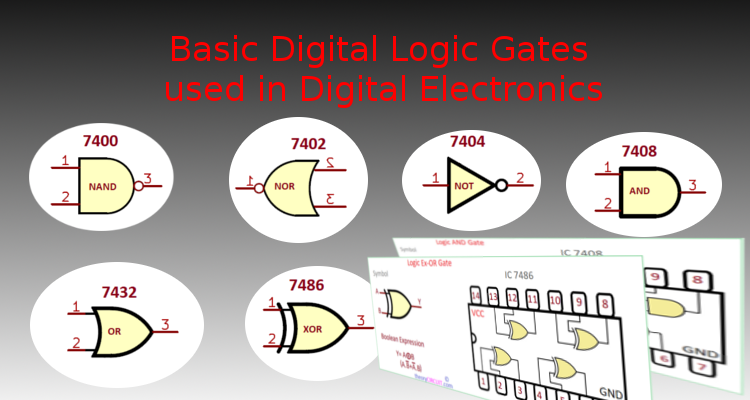
In this Modern Tech Century Computers and Smart phones plays vital role in our day to day life. When ever we use those device there will be some background operation happens by using Binary digits 0 and 1 in logic term we can say it as LOW for 0 and HIGH for 1. The Elements that perform Logical operations on binary inputs are called as Digital LOGIC Gates. These Gates are the basic building blocks of Digital circuits, Microcontrollers and Microprocessors. These Logic Gates gives specific output by manipulating binary input data that is 0s and 1s. Here is the list of Basic Digital Logic Gates used in Digital Electronics with truth table and Integrated circuit Pinout.
Digital Logic Gates are designed to perform Logic Functions, and the Logic gates can be combined together to perform complex combinational logic sequences. Logic Gates can be made by using discrete components like Transistor, Diodes, Resistors etc.., for the speed of operation and reliability most Integrated circuits are using only Transistors to form Logic Gates, this is called as TTL that is Transistor Transistor Logic. Some Integrated Circuits uses Fast and Low Power CMOS based MOSFETs to form digital Logic Gates IC 74XX and 4000 series are the best examples.
NAND Gate using Transistor
Basic Digital Logic Gates
Types of Logic Gates starts with NAND and NOR gate and we can construct any following Logic Gates by using either NAND gate s or NOR gates that why these two are called as Universal Logic Gates.
- Logic NAND Gate
- Logic NOR Gate
- Logic AND Gate
- Logic OR Gate
- Logic Ex-OR (XOR) Gate
- NOT Gate (Logic Inverter)
Logic NAND Gate

Logic NAND Gate performs Multiplication (Logic AND) operation between Binary inputs A, B then inverts output. The NAND gate is a combination of an AND gate followed by a NOT gate. It produces a low output only when all inputs are high.
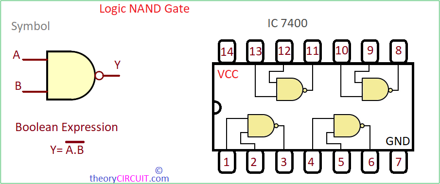
7400 is a quad 2 input NAND gate Integrated Circuit. Typical power supply voltage for the 7400 series is in the range of 4.5 Volts to 5.5 Volts DC. The Logic HIGH input usually around 2 volts or more of the power supply voltage, while the Logic LOW input is typically around 0.8 volts or less, Ground also considered as LOW. The Logic HIGH level output voltage is close to the power supply voltage that is VCC applied to the IC, and the logic LOW level output voltage is close to the Ground supply.
Logic NOR Gate
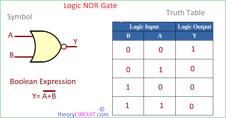
Logic NOR Gate performs Addition (Logic OR) operation between Binary inputs A, B then inverts output. The NOR gate is a combination of an OR gate followed by a NOT gate. It produces a low output only when at least one input is high.
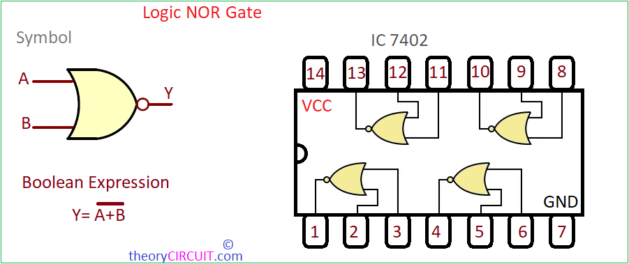
7402 is a quad 2 input NOR gate Integrated Circuit. Typical power supply voltage for the 7402 series is in the range of 4.5 Volts to 5.5 Volts DC. The Logic HIGH input usually around 2 volts or more of the power supply voltage, while the Logic LOW input is typically around 0.8 volts or less, Ground also considered as LOW. The Logic HIGH level output voltage is close to the power supply voltage that is VCC applied to the IC, and the logic LOW level output voltage is close to the Ground supply.
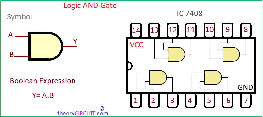
Logic AND Gate

Logic AND Gate performs Multiplication operation between binary inputs A,B which can be denoted as A&B. The AND gate produces a high output (1) only when all its inputs are high. It essentially performs the logical AND operation.
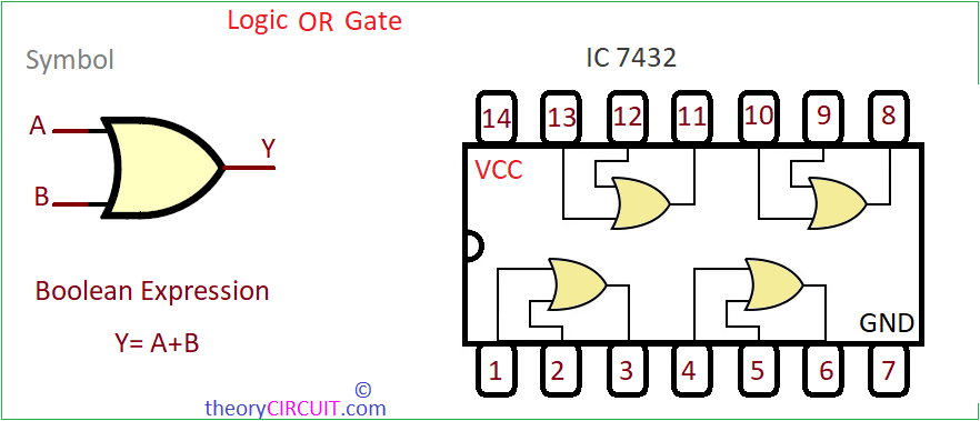
Logic OR Gate
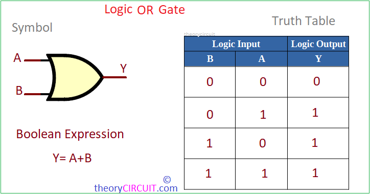
Logic OR Gate performs Addition operation between binary inputs A,B which can be denoted as A+B. The OR gate produces a high output (1) when any of its inputs is high. It essentially performs the logical OR operation.
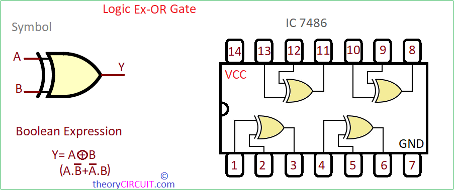
Logic Ex-OR (XOR) Gate
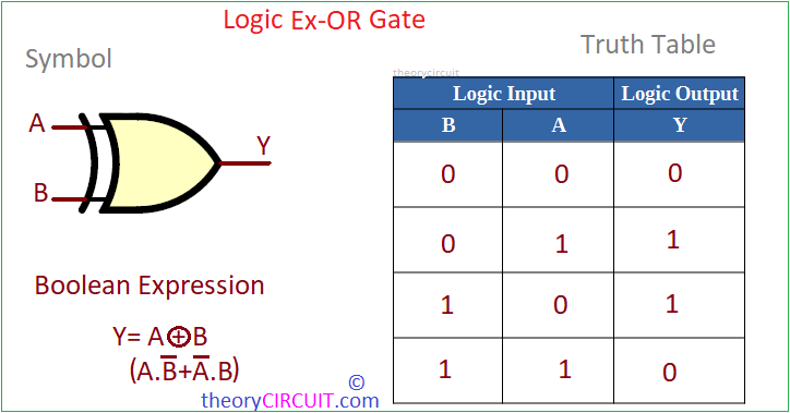
Logic Ex-OR (XOR) Gate performs Exclusive Addition operation between binary inputs A,B which can be denoted as A⊕B. The XOR gate produces a high output (1) when the number of high inputs is odd. Produces a LOW (0) output when all inputs are same.
NOT Gate (Logic Inverter)
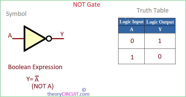
NOT Gate also known as an inverter, the NOT gate complements its input. If the input is high, the output is low, and vice versa. If the input is A then output is called as A bar.
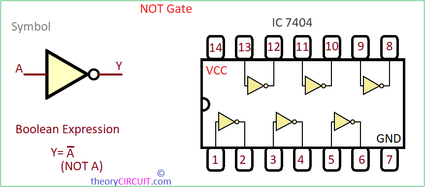
7404 is a Hex Inverter or NOT Gate Integrated Circuit, It contains Six independent inverter gates. Each gate takes an input signal and produces the complementary output. Typical power supply voltage for the 7404 series is in the range of 4.5 Volts to 5.5 Volts DC. The Logic HIGH input usually around 2 volts or more of the power supply voltage, while the Logic LOW input is typically around 0.8 volts or less, Ground also considered as LOW. The Logic HIGH level output voltage is close to the power supply voltage that is VCC applied to the IC, and the logic LOW level output voltage is close to the Ground supply.
Assalam-o-Aliqum
Mashallah these materials are most helpful to know digital electronics , logic gates and how to use in circuits. Although I belongs to chemical engineering but I inspired to know the binary system i digital electronics.
Thanks to all of you to prepare like these material .