Last Updated on March 16, 2024
Remote access to Electrical devices are makes us comfortable and If you can control Electric device with Clap then it makes you very joyful and here we have prototype a simple Clap ON Clap OFF switch using 555 timer and this circuit can help us to control any electric device, here for an example we have taken electric bulb.
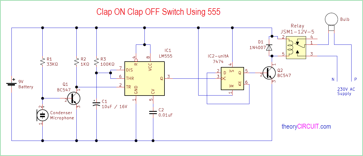
In this circuit 555 timer IC and 7474 dual positive Edge triggered D-type flip flop are used and Relay device control high volt electric appliances.
Circuit Diagram
Components Required
- Condenser Mic
- IC 555
- IC 7474
- Relay 9V
- Transistor BC547 NPN = 2
- Resistor 33KΩ, 1KΩ, 100KΩ each one
- Capacitor 10μF/16V, 0.01μF each one
- Diode 1N4007
- 9V Battery
Construction & Working
This circuit constructed in two parts, they are Clap detecting & trigger circuit and Switching circuit. The first one is consist of Condenser microphone and monostable multivibrator configured 555 timer.
Here Mic output is connected with trigger Input of timer IC, then Output from the timer IC is connected with the clock Input of D flip flop. The pulse output form the timer is monopulse and duration of this pulse is depends on timer Elements R3 and C1 values.
The D flip flop detect positive edge in pulse and changes its state accordingly. Output Q is connected to the Q2 transistor base and this transistor makes Relay coil ON or OFF.
When the clap occurs condenser microphone produce spike output and this will triggers timer IC then mono pulse produced and applied to flip flop clock input, here the flip flop detects positive edge of pulse and changes its state to either ON or OFF depends on the current state.
[stextbox id=’alert’]This Circuit Involved in handling of High volt AC supply, Handle with extreme care.[/stextbox]