Last Updated on March 16, 2024
Timer IC 555 has many possibilities to entertain electronic engineers and make productive in electronic circuit designs. Here simple and easy circuit clock ticking sound circuit using 555 designed with few easily available components, and it can be used in many ways.
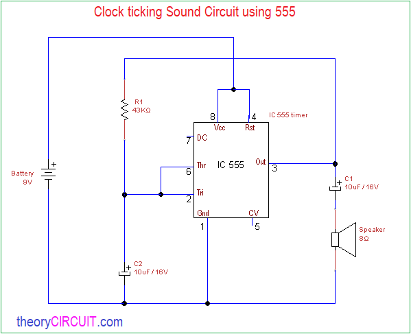
This circuit works as a Astable multivibrator and produce square pulse at output approximately one second each, at the output speaker is connected to produce clock ticking sound. Jtron 8 ohm speaker is enough to produce better sound output.
Circuit Diagram
Components Required
- IC 555
- jtron 8 ohm speaker
- Resistor 43KΩ
- Capacitor 10μF = 2
- Battery 9V
Construction & Working
To make timer IC 555 as a Astable multivibrator pin 8 and Reset pin 4 are connected together to positive supply, Ground pin 1 is connected to the negative supply of battery and trigger pin 2, threshold pin 6 are connected between timing Resistor R1 and timing Capacitor C2. Output pin 3 is connected with speaker through C1 Capacitor and R1 Resistor.
Control Voltage pin 5 and Discharge pin 7 are not connected with any components, When the output pulse reach C1 it get charged then discharge through Speaker it makes the speaker to produce better ticking sound.
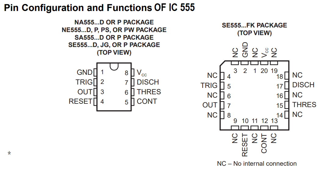
IC 555 Timer
It would be better to use a 36kΩ resistor as opposed to a 43kΩ resistor. With a 43kΩ the frequency is 1.68Hz (T= 0.596). With a 36kΩ resistor the frequency is 2.004Hz T= 2 x 0.693 x 36000 x 0.00001 = 0.49896