
Last Updated on March 16, 2024
For better operation every electronic circuit needs best Power supply source and mostly electronic components are requires Regulated DC power supply and some applications needs Dual power supply source that is Positive (+V), Ground (GND), Negative (-V).
What is Dual Power Supply?
A Dual Power Supply Circuit is a type of power supply that provides two independent voltage outputs from a center tapped AC source, Those dual power supply will be Regulated DC positive and negative supply. Dual power supply is widely used in many electronic applications, Especially in analog and operational amplifier applications, a dual power supply is often required to provide both positive and negative voltages. This allows the circuit to operate with signals centered around zero volts. This article helps you to built Dual power supply circuit by using step down transformer and linear voltage regulators.
Most electronic circuit and application requires DC voltage range mostly falls in 5, 12 and 15 Volts, hence three types of dual power supply circuit listed as,
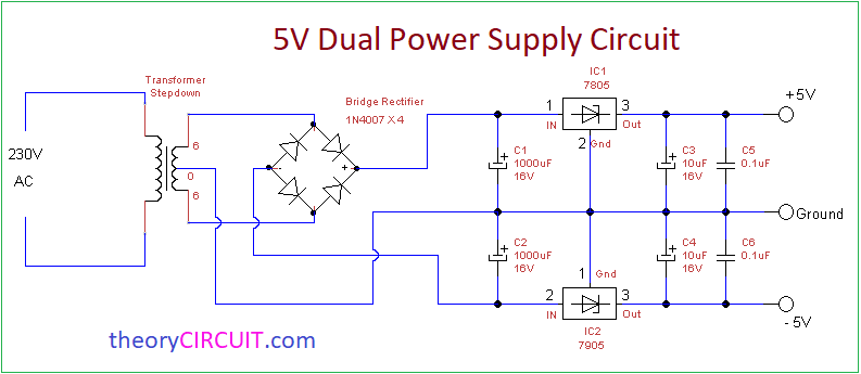
- 5 Volt (-5V GND +5V)
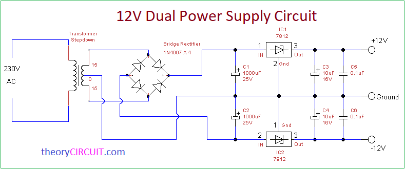
- 12 Volt (-12V GND +12V)
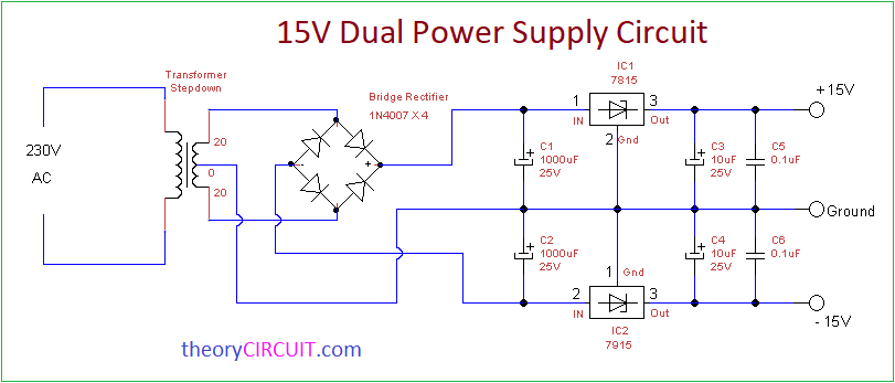
- 15 Volt (-15V GND +15V)
All circuit have individual step down transformer and voltage regulators, you may include LED indicator if you need.
5 Volt Dual power supply circuit diagram
12 Volt Dual power supply circuit diagram
15 Volt Dual power supply circuit diagram
Required Components
- Step down Transformer – center tap (6 or 15 or 20 VAc) depends on your need
- Bridge Rectifier Module or (1N4007 diode X 4)
- Capacitor 1000uF = 2, 10uF = 2, 0.1uF = 2. (Voltage range varies depends on circuit output voltage)
- Regulator IC (78XX = Positive), (79XX = Negative) choose voltage range depends on your need.
Construction & Working
For all above three circuit construction and working methods are same but the components specifications only change depends on output voltage range. Step down transformer is reduces the amplitude of input AC 230 volt to 6-0-6 Vac or 15-0-15 Vac or 20-0-20 Vac depends on its specification.
Low voltage AC supply from secondary winding of transformer is fed into Bridge Rectifier module (1N4007 X 4), then rectified DC output supply filtered by using filter capacitors C1 and C2, here C1 capacitor in all circuit filters positive side and C2 capacitor in all circuit filters negative side.
Voltage Regulators
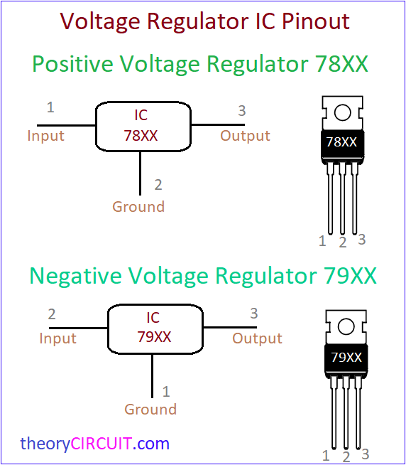
Voltage Regulator 78XX is responsible to regulate the positive side of DC voltage and 79XX is responsible to regulate the negative side of DC Voltage. Pin configuration of these two voltage regulators are illustrated and the connections are made as mentioned in the pinout.
At the output side Capacitors C3, C4 removes any kind of ripples in DC supply and Capacitor C5, C6 removes high freq ripples if any at the positive and negative side of DC output. The common Ground supply derived directly from the center tap of transformer (0) and acts as Ground (GND) terminal for +V and -V DC supply output.
Application notes
Some Audio Amplifiers or Operational Amplifiers and Power amplifiers are requires these kind of dual power supply.
For low voltage DC motor Direction control we can use these power supply circuit.
Choose the Transformer and Diode current rate depends on your need.
In your 12V dual power supply circuit, are you planning to implement a voltage regulator for stable output, and do you have any specific considerations for ripple rejection and load regulation? Additionally, are there particular applications or devices you intend to power with this circuit?
Hi smith
To enhance ripple rejection in a regulator circuit, you can incorporate filter capacitors at the input and output. For load regulation, ensure a stable voltage output under varying loads by selecting an appropriate regulator (here we used 7812) and adjusting feedback components. Additionally, using low equivalent series resistance (ESR) capacitors can improve both ripple rejection and load regulation.
And this design is for general purpose +12V and -12V supply.