
Last Updated on April 9, 2024
Three terminal Fixed Positive Voltage Regulators 78XX series are most usable on board Voltage regulators available in the market. This device being used for its characteristics like elimination of noise and distribution problems associated with single rail supply regulation, up to 1.5A output current delivering capability and internal Thermal overload protection. It requires just filtered DC Voltage and no external biasing components for to give fixed regulated DC output. It comes in TO-220 package with provision for heat sink. Here we are going to design Variable DC Power Supply Circuit using IC 7812 with the help of voltage divider setup and feedback.
When you are designing power supply circuit with some desired maximum output Voltage, use little higher Input Voltage to get non sink output from voltage regulators. For an example IC 7812 needs minimum 14 Volt Input, if you apply exact 12V input then there will be some internal sink and you won’t get 12V output. This can be applied for all kind of fixed voltage regulators and Zener diode based circuit.
For AC to DC Rectification we have used Bridge Rectifier module W04M, you can use Four PN junction diode (should have 1A current range) to form bridge. For operation details about Full wave Bridge Rectifier read here.
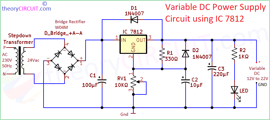
Circuit Diagram
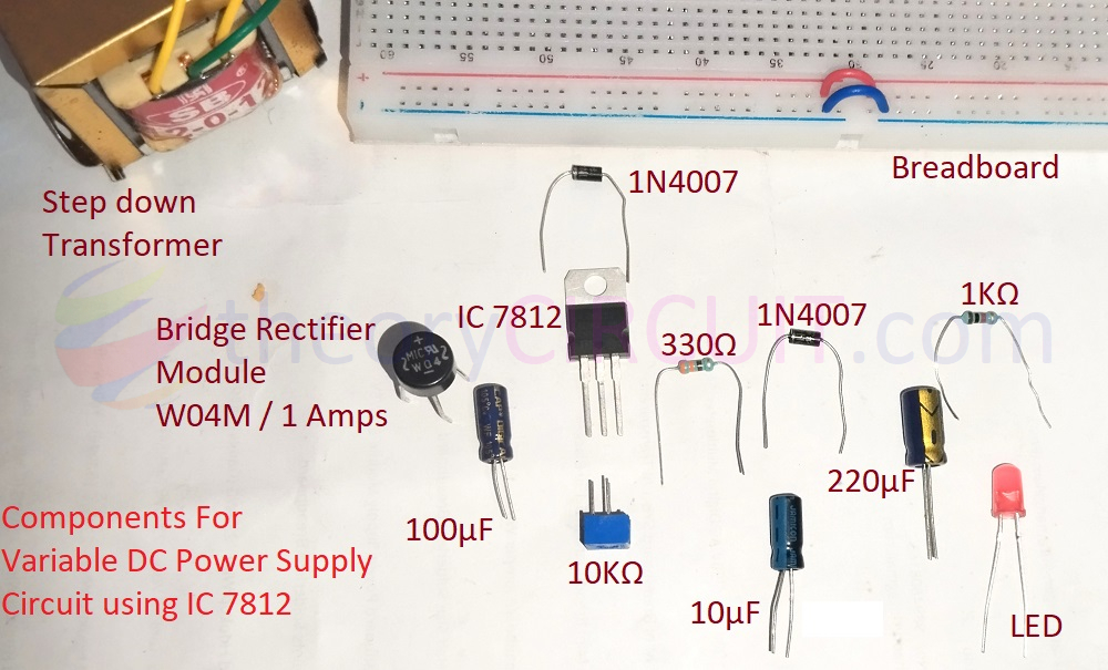
Components Required
- Step down Transformer (230V to 0-24Vac)
- Bridge Rectifier Module W04M
- Fixed Positive Voltage Regulator IC 7812
- Diode 1N4007 = 2
- LED
- Electrolytic Capacitor 100μF, 10μF, 220μF each one
- Variable Resistor (Trimpot) 10KΩ
- Resistor 330Ω, 1KΩ each one
Working Video
Construction & Working
Construction starts with Selecting Step down transformer, here we have used 230V AC input primary and 24V AC secondary Step down transformer. 24V AC supply is directly applied to bridge rectifier module, it rectifies AC sinusoidal signal into Pulsating DC, Filter Capacitor C1 makes pulsating DC into linear DC by making charging and discharging process.
Now the Fixed Voltage Regulator IC 7812 Receives Input supply at pin 1 and the GND pin is connected between Voltage Divider setup made by R1 and RV1 Resistors. Here RV1 is a Variable Resistor (Trimpot), by changing this value we can obtain different voltage level in the junction of voltage divider. A Diode 1N4007 (D1) is connected between Output and Input terminal of 7812 to prevent reverse voltage from load or inductive load transients.
Another Diode (D2) is connected at the output terminal to bypass any negative ripples to Capacitor C2 and the junction of these two components is connected between Voltage divider junction. Capacitor C3 makes final Filtering of DC supply output from 7812 and the LED with series Resistor R2, indicates the presence of power supply.
As per the datasheet claim for Adjustable Output Regulator or variable voltage regulator circuit,
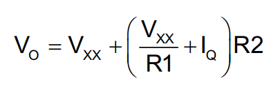
here, Vo is output voltage, Vxx is the nominal output voltage of fixed regulators, and R2 is Variable Resistor.
The above formula can be simplified as per our Schematic,
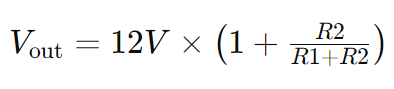
Here, R2 is Variable Resistor RV1 (Trimpot 10KΩ) and R1 is 330Ω Resistor. Use direct value of RV1 as 1Ω to 10000Ω in the formula.
This circuit will give output Voltage from 12V to 22V. Depends on the Resistor tolerance value it may slightly change.
Example Calculation,
Vout = 12 * (1+ (1000/330+1000))
Vout = 12 * (1+(1000/1330))
Vout = 12 * (1+0.7518)
Vout = 12*1.7518
Vout = 21.02 = 21 Volt
Remember to apply enough input Voltage to get desired output voltage, maximum ability of this circuit is 24V, so to get 24 Volt output you need to apply at least 26V DC as input to the IC 7812 in this Variable DC Power Supply Circuit.
7812 Pinout
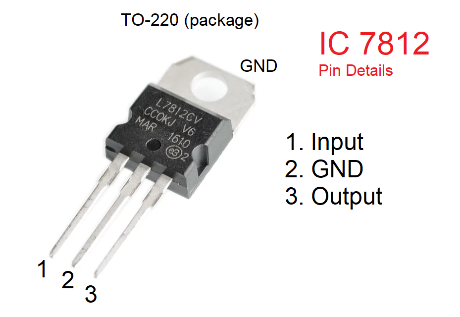
Most 78XX series Fixed positive voltage regulators may have this pinout in TO-220 Three terminal package. Always refer datasheet for exact pin configuration of electronic components.