Last Updated on June 29, 2024
Interfacing RGB LED with ESP32 board have tons of applications. It is very easy and convenient to control RGB LEDs through ESP32 board. We know that by mixing primary colors Red, Green and Blue we can make millions of colors. Here we used PWM values from 0 to 255 to control all three primary colors to get desired output color. Here 0 means OFF and 255 means Full Brightness from the LED.
Two different RGB LEDs available based on their common pins.
- Common Anode RGB LED
- Common Cathode RGB LED
It requires minimum forward voltage between 2V to 3V to operate.
This is example for Through hole RGB LEDs, make sure about the terminals and their color before implementing it in a circuit.
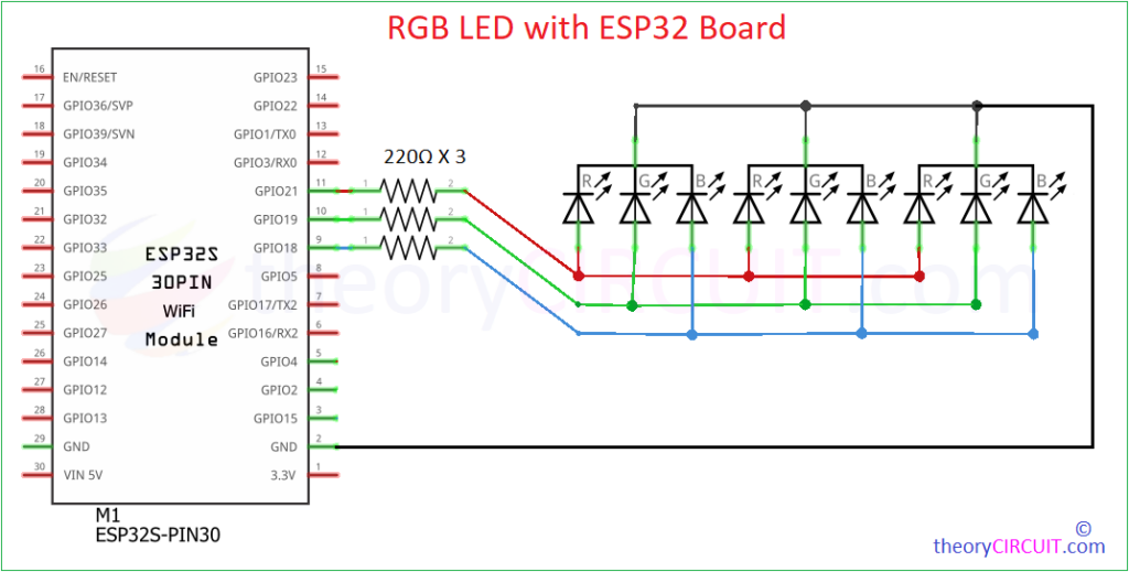
Circuit Diagram
Components Required
- ESP32 Board
- RGB LEDs (here we used Common Cathode)
- Resistor 220Ω = 3
- PC with Arduino IDE
Working Video
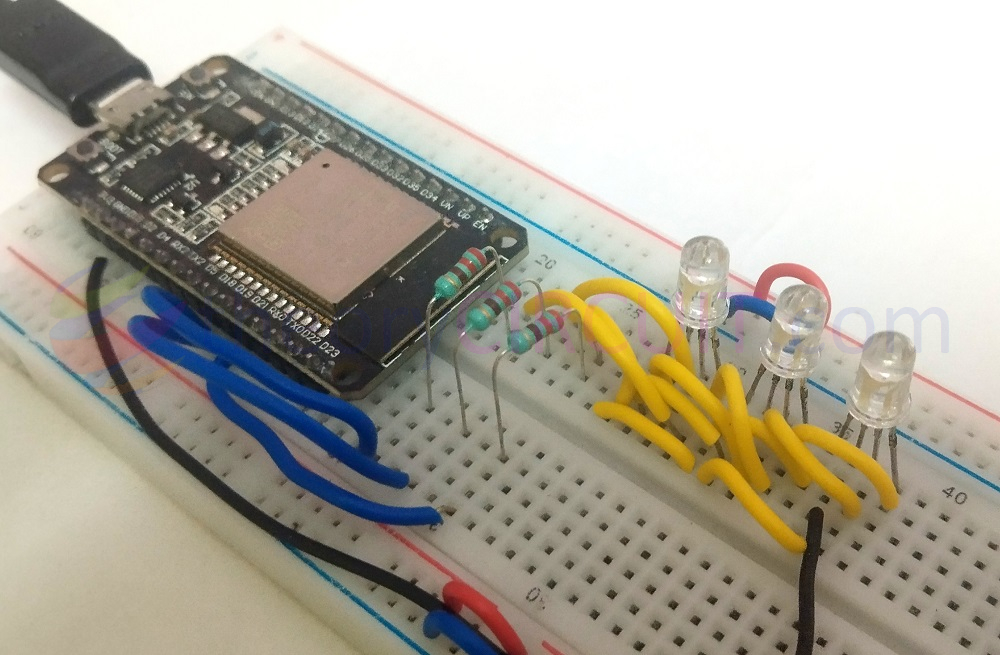
Construction & Working
Here we used three common cathode RGB LEDs and made an array. All three LEDs cathode pins connected to GND terminal of ESP32 board. Grouped color terminals are connected as follow.
- All Red Anodes connected to GPIO21 of ESP32 board.
- All Green Anodes connected to GPIO19 of ESP32 board.
- All Blue Anodes connected to GPIO18 of ESP32 board.
with three 220Ω Resistor in series. After the hardware connections upload the following code through Arduino IDE and observe the different pattern colors from RGB LEDs. If you are new to use ESP32 board with Arduino then read here to get started.
Code
// Define the common GPIO pins for each color
#define RED_PIN 21
#define GREEN_PIN 19
#define BLUE_PIN 18

void setup() {
  // Initialize the pins as outputs
  pinMode(RED_PIN, OUTPUT);
  pinMode(GREEN_PIN, OUTPUT);
  pinMode(BLUE_PIN, OUTPUT);
}

void loop() {
  colorFade();    // Fade colors in and out
  colorCycle();   // Cycle through colors
  blinkEffect();  // Blink all LEDs on and off
}

// Function to set the color of all RGB LEDs
void setColor(int redValue, int greenValue, int blueValue) {
  analogWrite(RED_PIN, redValue);
  analogWrite(GREEN_PIN, greenValue);
  analogWrite(BLUE_PIN, blueValue);
}

// Function to fade colors in and out
void colorFade() {
  for (int i = 0; i <= 255; i++) {
    setColor(i, 0, 0);  // Fade in red
    delay(5);
  }
  for (int i = 255; i >= 0; i--) {
    setColor(i, 0, 0);  // Fade out red
    delay(5);
  }
  for (int i = 0; i <= 255; i++) {
    setColor(0, i, 0);  // Fade in green
    delay(5);
  }
  for (int i = 255; i >= 0; i--) {
    setColor(0, i, 0);  // Fade out green
    delay(5);
  }
  for (int i = 0; i <= 255; i++) {
    setColor(0, 0, i);  // Fade in blue
    delay(5);
  }
  for (int i = 255; i >= 0; i--) {
    setColor(0, 0, i);  // Fade out blue
    delay(5);
  }
}

// Function to cycle through different colors
void colorCycle() {
  setColor(255, 0, 0);   // Red
  delay(500);
  setColor(0, 255, 0);   // Green
  delay(500);
  setColor(0, 0, 255);   // Blue
  delay(500);
  setColor(255, 255, 0); // Yellow
  delay(500);
  setColor(0, 255, 255); // Cyan
  delay(500);
  setColor(255, 0, 255); // Magenta
  delay(500);
  setColor(255, 255, 255); // White
  delay(500);
}

// Function to blink all LEDs on and off
void blinkEffect() {
  for (int i = 0; i < 5; i++) {
    setColor(255, 255, 255); // On
    delay(500);
    setColor(0, 0, 0);       // Off
    delay(500);
  }
}
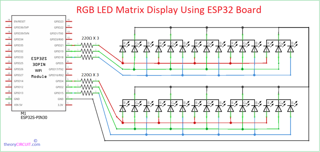
If you want to make matrix, here is the simple example 2X5 RGB LED Matrix with ESP32 board.
Simple Code
#define ROWS 2
#define COLS 5

int redPins[ROWS] = {21, 4};
int greenPins[ROWS] = {19, 2};
int bluePins[ROWS] = {18, 15};

int ledMatrix[ROWS][COLS][3] = {0};

void setup() {
  for (int i = 0; i < ROWS; i++) {
    pinMode(redPins[i], OUTPUT);
    pinMode(greenPins[i], OUTPUT);
    pinMode(bluePins[i], OUTPUT);
  }
}

void loop() {
  displayPattern();
}

void displayPattern() {
  for (int row = 0; row < ROWS; row++) {
    for (int col = 0; col < COLS; col++) {
      setColor(row, col, random(255), random(255), random(255));
      delay(100);
    }
  }
}

void setColor(int row, int col, int red, int green, int blue) {
  analogWrite(redPins[row], red);
  analogWrite(greenPins[row], green);
  analogWrite(bluePins[row], blue);
}


