
Last Updated on March 16, 2024
Frequency divider circuits are takes important place in digital logic circuits and some analog multiplex circuits, making perfect frequency divider is quite complex thing, by using timer IC 555 and decade counter IC CD4017 we can create simple and easy to construct frequency divider circuit.
We know frequency dividers makes any input frequency f divided by n integer value (f / n), the following circuit takes input frequency f and gives output frequency as (f / 2), (f / 4) and (f / 6). Here timer IC used to generate square pulse signal and it can be tuned to different frequency by variable resistor. Exact divided frequency output is taken from decade counter Q1 pin.
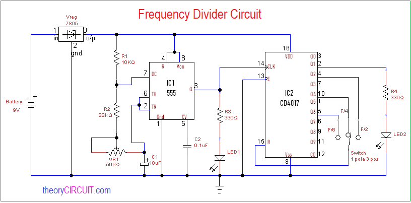
Circuit Diagram
Construction and Working
This frequency divider circuit made by two sections one is input frequency generator and another one is decade counter/divider circuit. IC 555 is configured as astable multivibrator, timing resistor (R1, R2) and variable resistor VR1 are connected with timing capacitor C1, discharge pin7 is connected between R1 and R2 then threshold pin6 and trigger pin2 are connected between VR1 and C1. 5V vcc applied to the bias pin8 and reset pin4, here control voltage pin5 is connected to ground through 0.1 uF C2 capacitor. Output pin 3 is connected with clock pin of decade counter ic and LED1, this LED indicates the input frequency.
IC 4017 takes input clock at pin 14 and provides decade output from Q0 to Q9. To convert this into frequency divider we have taken output from Pin 2 and connected with LED2 through R4, this will visually indicate the output frequency through blinking. Active low enable pin 13 is grounded and Reset pin 15 is connected with three way switch towards Q2 for F/2 output selection, Q4 for F/4 output selection and Q6 for F/6 output selection. When we use oscilloscope at output pin 2 we can obtain divided output frequency.
Output Waveform
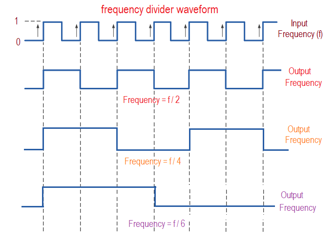
First signal represents input frequency (f) and output frequency (f/2), (f/4) and (f/6) are shows the divided frequency results.
Neat circuit. Can it divide by 8?
The circuit is ok. But the “output waveform” diagram seems to be wrong.