Last Updated on March 16, 2024
Need of dual power supply for certain circuit is necessary, if you use any operational amplifier or some special IC means you need to give +ve, GND and -ve supply, some times we use battery as a power source so we can not get these supply, to avoid this problem here we propose simple circuit.
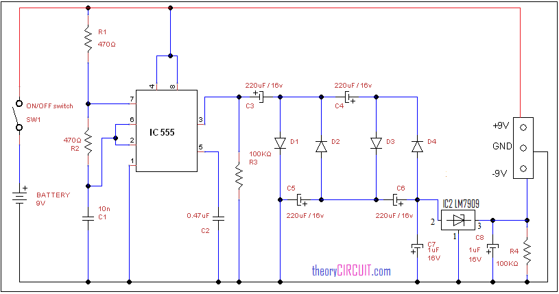
Circuit diagram for dual power supply from battery
Construction and Working
Timer IC 555 is used here to oscillate pulse hence we can rectify these pulse into -ve supply by using diodes and regulation of negative voltage can be done through IC 79xx.
The main power source battery gives +ve 9 Volt supply this is directly fed to the output connector, with the help of R1, R2 and C1 timing components the timer IC produces pulses at the output this pulse converted to negative direction and regulated by the negative regulator IC7909 and then this negative voltage and GND supply given at the output connector.


You probably already have been notified that this circuit diagram cannot and will not work. Since the output connector has NO -9 Volts supplied to it. The -9 Volt output needs to be connected to the #3 pin of the LM7909… I know!
Larry Frew
excuse me my mistake and now its live!