
Last Updated on June 8, 2024
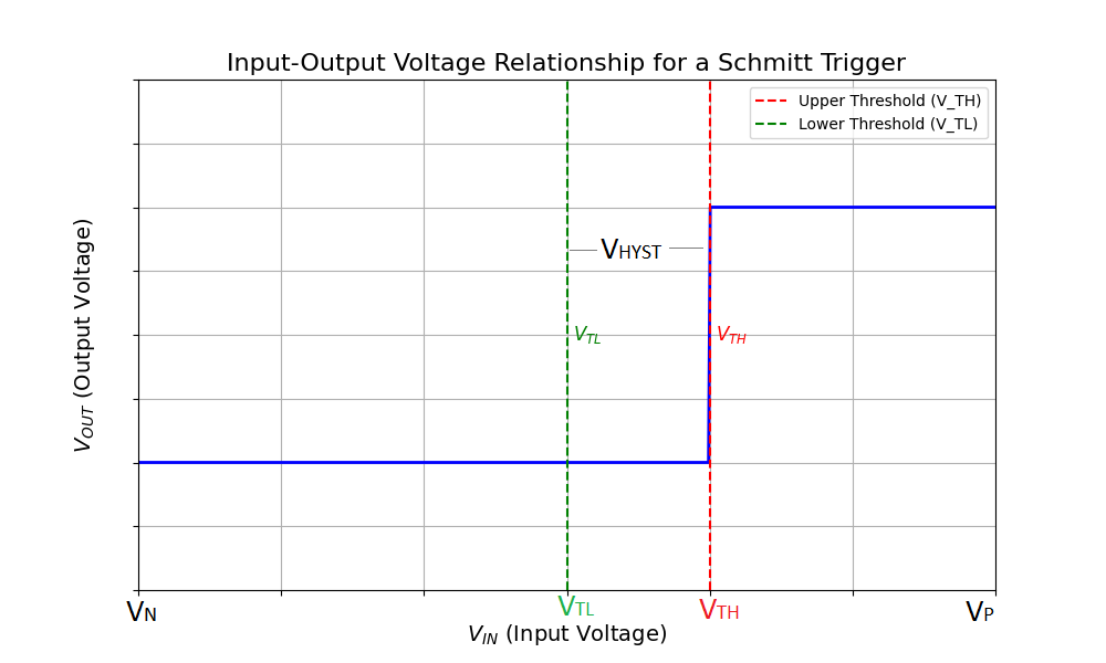
Typical Schmitt Trigger is a comparator circuit that incorporates Hysteresis that is, it have two different threshold voltage levels, one is for transitioning from LOW to HIGH and another for transitioning from HIGH to LOW. So this Schmitt trigger produce stable square wave (digital) output from any kind of analog input signal. Schmitt trigger circuit is mainly used for generating square waves from a noisy sine wave or other analog signal. Schmitt trigger can give either Non Inverting output or Inverted square output. In the following experiment, we are going to design Schmitt Trigger using IC 555. This timer based circuit gives Inverted Square output for sine wave input.
As we know Timer IC 555 contains two independent internal comparators and RS Flip-Flop and here we are going to use that to form Inverted Schmitt Trigger. Different switching threshold voltage and the input output voltage relationship for a Schmitt trigger is shown in graph.
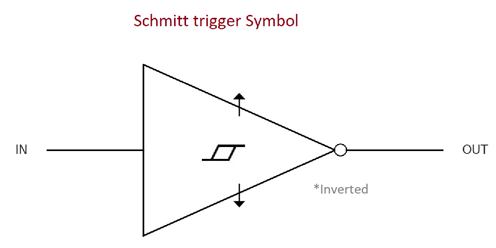
Schematic symbol of Inverted Schmitt Trigger
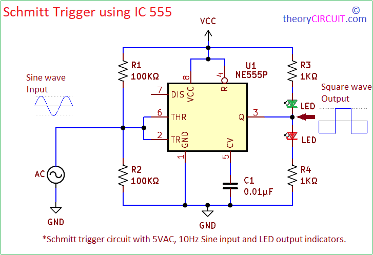
To form Schmitt trigger using timer IC 555, we need two external resistors with equal resistance value. To test the output here used two LEDs at the output.
Schmitt Trigger using IC 555 Circuit Diagram
Components Required
- Timer IC NE555P = 1
- Resistor 100KΩ = 2
- Resistor 1KΩ = 2
- Capacitor 0.01μF = 1
- 5mm LED Green, Red = each one
- Sine wave input source
- DC power supply 5V to 9V
Construction & Working
3 This circuit forms hysteresis between 1/3 Vcc and 2/3 Vcc, through Threshold and Trigger pins because these pins are connected with Interna3cel comparators of 555 and by 1/3 Vcc level input signal, comparator connected with Trigger pin gives output to internal flip-flop and makes it RESET. When the analog input voltage reaches 2/3 Vcc level and then comparator connected with threshold pin gives output and makes internal flip flop in SET condition.
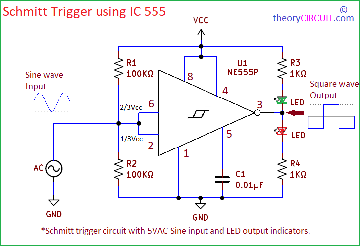
So the output changes LOW and HIGH depends on the analog input signal. Here we have applied 5V amplitude AC sine wave with 10 Hz frequency and observed output through LEDs.
Working Video
Waveform
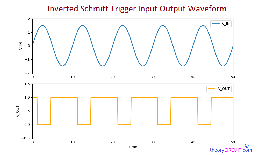
Input and Output Waveform of Schmitt Trigger Circuit using Timer IC 555