Last Updated on March 16, 2024
The DC motor speed control circuit is designed using IC LM3578 switching regulator, this IC can be used for DC to DC voltage conversions such as buck, boost and inverting applications.
About LM3578
The LM3578A stands out as a switching regulator from Texas Instruments, effortlessly adaptable for diverse DC to DC voltage conversion setups, including buck, boost, and inverting configurations. Noteworthy is its distinctive comparator input stage, featuring separate pins for both inverting and non-inverting inputs, along with an internal 1.0V reference to each input. This characteristic streamlines circuit design and PCB layout, aligning well with your interests in electronic product design. The output, supporting up to 750 mA, boasts collector and emitter output pins, enhancing design flexibility. The external current limit terminal is adaptable to either ground or Vin terminal, depending on the application. Additionally, the LM3578A incorporates an onboard oscillator, facilitating easy adjustment of the switching frequency (from <1 Hz to 100 KHz) with a single external capacitor. With an operational voltage range of 2V to 40V, this IC, packaged in PDIP/SOIC, offers versatility for your electronic circuit projects. Refer Datasheet for more details.
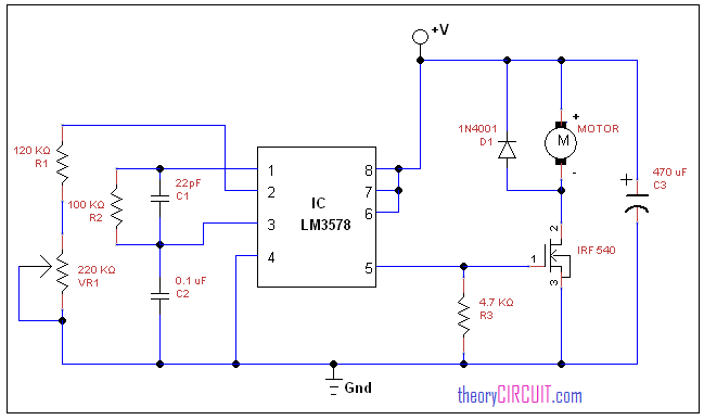
Circuit diagram
Components List
- IC LM3578
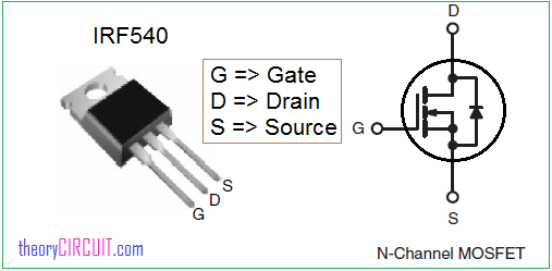
- MOSFET IRF540
- Diode 1N4001
- Capacitor 470μF/25V, 22pF, 0.1μF
- Resistor 120KΩ, 100KΩ, 4.7KΩ
- Variable Resistor 220KΩ
- DC Motor
Construction and working
The DC motor is connected with DC power supply and output driver IRF 540 MOSFET, the diode D1 provides protection from back EMF, the MOSFET gate terminal is driven by output signal from pin 5 of LM 3578, Pin 8, 7 and pin 6 are shorted together and connected with positive supply, components C1, C2 and R2 are connected between pin 1, 3 and ground supply, pin 2 of LM3578 is connected with R1 and variable resistor VR1, by varying VR1 we can vary the speed of DC motor.
Datasheet
You can get datasheet of IC LM3578 here.
You can get datasheet of IRF 540 here.
IRF540 pinout
Very nice circuit.
What component values would need to be changed to use this circuit with a 24v supply driving a 24v 800w permanent magnet brush motor?
Hi Wade Nelson,
LM3578 is a Switching Regulator, provides Output current up to 750 mA. You need power Transistor or power MOSFET H-bridge Motor driver circuit to drive 24v 800w permanent magnet brushed motor. Consider “Brush Motor Controller, 24V 800W E-Bike Motor Brush Speed Controller” available in the internet if you are looking for e-bike DC Motor speed controller.