Last Updated on March 16, 2024
We know Lead Acid Battery is the most widely used rechargeable battery. This types of batteries are provide electricity through a double sulfate chemical reaction. Simply active materials on the batteries plates reacts with acid and provides electricity.
By applying proper voltage and current we can easily Recharge Lead Acid batteries. By providing proper recharge cycle duration we can extend the life of Lead Acid batteries.
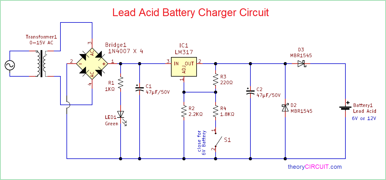
Circuit Diagram
Components Required
- Step down Transformer 0-15V AC (as per your requirements)
- Bridge Rectifier module or 1N4007 X 4
- Regulator IC LM317
- Resistors 1KΩ, 2.2KΩ, 220Ω, 1.8KΩ each one
- Capacitors 47µF/50V = 2
- LED green
- SCHOTTKY diode MBR1545 = 2
- on/off switch
Construction & Working
Lead Acid batteries are having medium lifespan and requires proper Recharge and Load circuits. If Lead Acid battery plate active materials are dissolved then battery will no longer sustain recharge cycle that means battery dies.
Maintaining Lead Acid battery with proper Recharge circuit can extend the lifespan. This circuit is designed to charge 6V and 12V battery and Switch S1 decides the output voltage. Here 4 Amps Step down transformer (0-15V AC) is used to reduce the 230V AC supply and then Bridge Rectifier module is used to convert AC supply in to DC supply, LED1 indicates the presence of DC supply and Positive voltage Regulator LM317 Regulates the DC Supply to Required level and by connecting R3, R4 Resistors with Adj pin this Regulator provides 6V output and disconnecting these Resistors output will rise to 12V.
Two SCHOTTKY Rectifier diodes are connected at the output to protect Battery and circuit from Reverse Current and Reverse polarity connections.
What can we use to replace mbr without affecting voltage?
Pode ser usado MBR360= SR360= SB360 ou MBR560= SR560=SB560 , todos esse funciona perfeitamente , pois o regulador LM317 não fornece mais que 1,5A !!!!
Hello! I haven`t seen any current limit component in this charge device. There are TWO voltage sources – and they are connecting in parallel. Who will win? The battery has a very small internal resistance 0.1 .This charger works in linear mode and has also small internal resistance. And who will win? The linear regulator will out of order (because it will be overheat).
P.S. You needs such like self-oscillating flyback : https://drive.google.com/file/d/18EuIlFOlerM6YO6gSNXuRzZe9O0BapSy/view?usp=share_link
The lm317 has a built in current limit of 1.5A