Last Updated on March 16, 2024
We know the Magnet has two Polarity called North pole and South pole, if each poles attracts each other definitely one is North and another one is South pole, if each other repels each then these two are same pole. But here we can’t decide which is South and North pole, to make the task easy the following simple Magnet Polarity Detector Circuit helps you lot.
Magnet Polarity Detector Circuits are designed by using Hall effect sensors, Hall effect sensors are widely used in various applications like robotics, automotive, and consumer electronics, to detect the presence of a magnetic field and determine its polarity. These sensors work based on the Hall effect, which is the production of a voltage difference across an electrical conductor inside the hall effect sensor, when a magnetic field is applied perpendicular to the current flow.
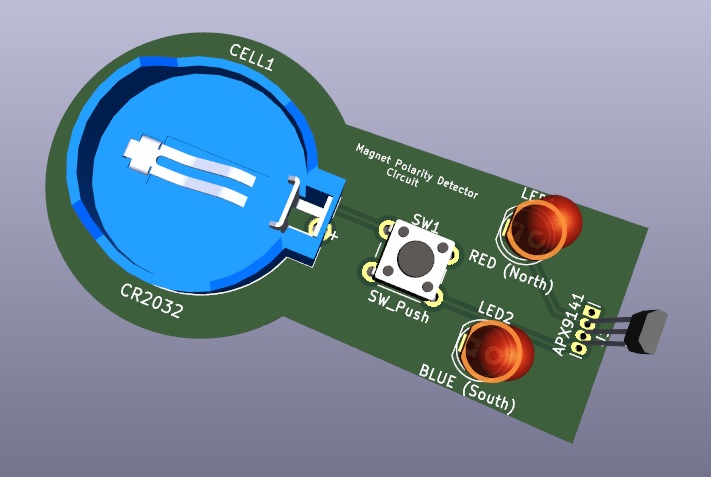
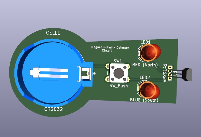
Magnet Polarity Detector Circuit Diagram
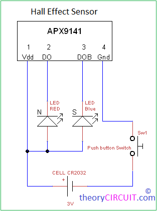
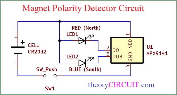
This circuit constructed by using few easily available components, main part of this circuit is APX9141 Hall Effect sensor. It has Hall element and two different outputs as DO and DOB by using these output we can easily detect poles of Magnet.
Here the Red LED connected in DO (pin 2) it represents North pole, and Blue LED connected in DOB (pin 3) it represents South pole.
This sensor can operates in 3V hence the CR2032 3V Cell is placed to provide bias.
Another version of Magnet Polarity identifier Circuit Diagram
Components Required for PCB (BOM)
| 1 | U1 | APX9141 | Allegro_SIP-4 | 1 | ||
| 2 | SW1 | SW_Push | SW_PUSH_6mm | 1 | ||
| 3 | CELL1 | CR2032 | BAT_BS-7-BLUE | 1 | ||
| 4 | LED1 | RED (North) | LED_D5.0mm | 1 | ||
| 5 | LED2 | BLUE (South) | LED_D5.0mm | 1 |
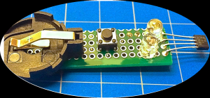
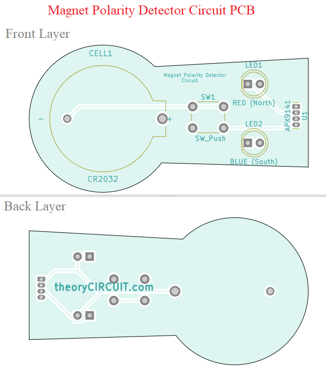
Magnet Polarity Detector Circuit PCB
Magnet Polarity Detector Circuit Gerber Files.
Interactive Board Viewer


PCB 3D View
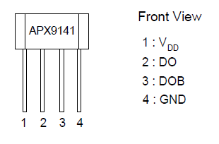
APX9141
Hall Effect Sensor IC with Reverse Voltage Protection from ANPEC.
Features
• On-chip Reverse Voltage Protection
• On-chip Hall Sensor
• Low Operating Supply Voltage : 3 V
• High Output Sinking Capability up to 400mA
• Versatile sensitivity and hysteresis setting
• Reliable and Rugged
• 4 pin TO-92M Package
Block Diagram

Datasheet
Good to know the things that can’t be found elsewhere.
Thanks for your appreciation 🙂