Last Updated on March 16, 2024
Simple Mobile phone detector circuit designed with few easily available components and we can detect any kind of active mobile phones with in a room or specific space. This prototype circuit will be useful for mobile restricted area and mobile detecting applications.
We know that every mobile phones operates under 800 MHz to 2100 MHz range of frequency spectrum and by detecting the electromagnetic signal of active mobile we can locate it. Mobile phone detector circuit detects only electromagnetic signals caused by active mobile phones and it can’t located switched off mobiles.
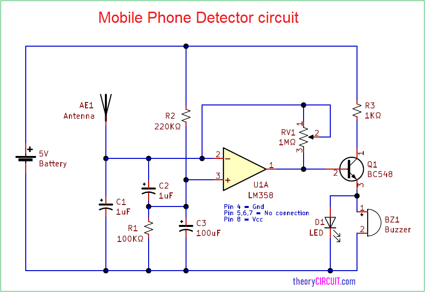
Circuit Diagram
Components Required
- IC LM358
- Buzzer
- LED (Red Color)
- Transistor BC548 (NPN)
- Variable Resistor 1MΩ
- Resistor 100KΩ, 220KΩ, 1KΩ
- Capacitor 1µF=2, 100µF
- generic GSM antenna or aerial antenna
Construction & Working
This circuit has electromagnetic pickup stage and amplification stage then output alert stage, first thing we need to place the low power dual operational amplifier IC LM358 with proper bias and we need only one operational amplifier from IC LM358 and left open other. Antenna to be connected to the Inverting input with Variable Resistor feedback path. Non inverting input pin placed between R2 and C3 capacitor. Output from the operation amplifier connected to the base terminal of Q1 transistor and buzzer, LED are connected at the emitter pin.
When this mobile phone detector circuit antenna detects active mobile electromagnetic signal then it converts into very low power electric signal, then this signal gets amplified by the LM358 operational amplifier, then output is applied to the buzzer and LED through switching transistor Q1 here buzzer and LED indicates the hidden mobiles through sound and blink.
لو تكرمت ارسل فيديو العمل
Translation
(If you would be so kind as to send a video of the work)
السلام عليكم لو تكرمت يرجى ارسال لي فيديو العمل
Translation
(Peace be upon you. If you would be so kind as to send me a video of the work)